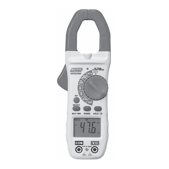
Major tech MTD70T Manuel d'instruction - Page 9
Parcourez en ligne ou téléchargez le pdf Manuel d'instruction pour {nom_de_la_catégorie} Major tech MTD70T. Major tech MTD70T 12 pages. 600a ac true rms digital clamp meter

3. Connect the test leads in parallel to the circuit under test.
4. Read the voltage measurement on the LCD display.
5.3. DC Voltage Measurements
1. Insert the black test lead into the negative COM terminal and the red
test lead into the positive V/Ω terminal.
2. Set the function switch to the V
3. Connect the test leads in parallel to the circuit under test.
4. Read the voltage measurement on the LCD display.
5.4. Resistance Measurements
1. Insert the black test lead into the negative COM terminal and the red
test lead into the positive V/Ω terminal.
2. Set the function switch to the Ω position.
3. Touch the test probe tips across the circuit or component under test. It
is best to disconnect one side of the device under test so the rest of the
circuit will not interfere with the resistance reading.
4. For Resistance tests, read the resistance on the LCD display.
5.5. Continuity Measurements
1. Insert the black test lead into the negative COM terminal and the red
test lead into the positive V/Ω terminal.
2. Set the function switch to the
3. Use SELECT Button to select . The display icons will change when the
SELECT button is pressed.
4. Touch the Test Probe tips across the circuit or component under test.
5. If the resistance is <50Ω, the buzzer tone will sound.
5.6. Diode Test
1. Insert the black test lead into the negative COM terminal and the red
test lead into the positive V/Ω terminal.
2. Set the function switch to
3. Use SELECT Button to select
SELECT button is pressed.
4. Touch the test probe tips to the diode or semiconductor junction under
test. Note the meter reading.
5. Reverse the test lead polarity by reversing the red and black leads. Note
the reading
6. The diode or junction can be evaluated as follows:
• If one reading displays a value (typically 0.400V to 0.900V) and the
other reading displays OL, the diode is good.
• If both readings display OL device is open.
• If both readings are very small or "0", the device is shorted.
position.
position.
position
. The display icons will change when the
9
