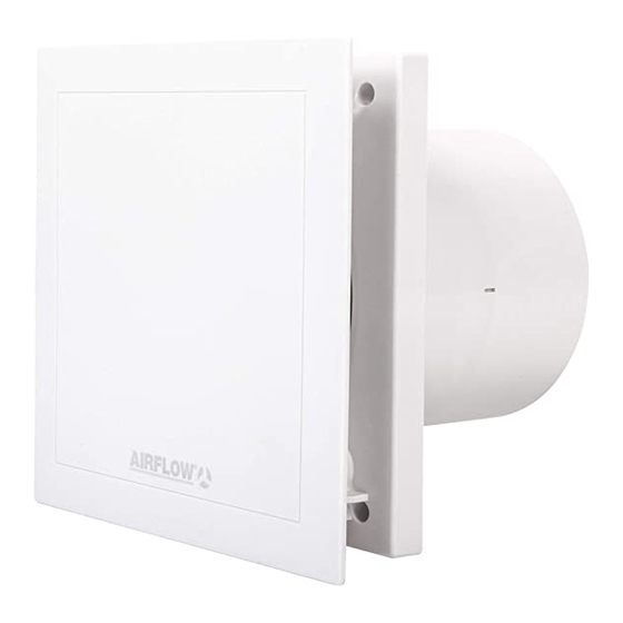
Airflow QT 120T Manuel d'installation et d'utilisation - Page 7
Parcourez en ligne ou téléchargez le pdf Manuel d'installation et d'utilisation pour {nom_de_la_catégorie} Airflow QT 120T. Airflow QT 120T 7 pages. Quietair 100/120mm axial fan
Également pour Airflow QT 120T : Instructions d'installation et d'utilisation (4 pages)

energy
Guaranteed Low Prices
þ
Huge Stock Available
þ
Airflow Stockist
Installation and Operation Instructions
þ
Wiring diagram overview
QT100T - 75(90)m
QT120T - 150(170)m
ion
ied
for
V to
WARNING
ese
Electrical connection:
es,
- Terminal N / L:
The supply voltage of 230 V is connected permanently to
terminal N/L
- Terminal 1:
The time functions are activated via terminal 1.
The following functions are implemented:
1. Start delay (0 sec, 45 sec, 90 sec, 120 sec)
DIP-switch S1-2 (see wiring diagram SS-920.2)
After switching on terminal 1, the fan starts first after the adjusted
delayed time. Thus a room can be entered for a short time (via
two-pole switch) e.g. during combined on/off switching with the
hes
light without the fan being started for operation. Factory setting
approx. 120 sec.
2. Operation with push-button switch
During start delay the fan can be switched on via terminal 1 with a
push-button switch at deactivated start delay (sampling pulse min.
0,5 sec.).
3. Run on time (6 min., 10 min., 15 min., 21 min.)
DIP-switch S3+4 (see wiring diagram SS-920.2)
After switching off terminal 1, the fan keeps running and switches
off after the adjusted time automatically. Factory setting approx.
15 min.
4. Interval operation (0 hrs., 8 hrs., 12 hrs., 24 hrs.)
DIP-switch S5+6 (see wiring diagram SS-920.2)
The fan can be put in adjustable time intervals into operation auto-
matically. After the adjusted run on time the fan switches off auto-
matically. The interval time starts after the last switch off process
on terminal 1 (time input), also with manual operation in the mean-
time (terminal 2). The manual operation does not have influence on
the interval operation. The turn-on time in the interval operation
corresponds to the adjusted run on time. Factory setting approx. 0
gs.
hrs.
se
In delivered condition the interval operation is deactivated. The DIP
switches have to be adjusted according to the table for a desired
interval.
em
5. Changing the factory setting
DIP-switch (see wiring diagram SS-920.2). Isolate the unit from the
mains electric supply !
- Terminal 2:
The continuous operation is activated via terminal 2 (see wiring
diagram SS-917). With activated time function, the manual stage
(terminal 2) is inactive.
Room lighting
In connection with the room lighting (terminal 1 or 2), a two-pole
switch must be used.
bulbs
.co.uk
3
/hr
Connection client
3
/hr
M1/... N
SS-917
M1/... NC
N
L
1 2
a)
b)
L
N
1
2
a) time function
a) Zeitfunktion
b) manual on
b) manuell Ein
Mon-Fri:
8:30am - 6:30pm
Internal functional principle / Jumper position
N
L
1
time function/- input
Zeit-Eingang
manual input
Manueller-Eingang
2
Jumper 1
A / B
N
L
1 2
Adjustment of DIP-switchs
QT ... T
S1
on
o
1 2 3 4 5 6
N
L
1 2
Important: Wiring in parallel
Wiring in parallel of several fans is not permitted.
- Jumper
Depending on the jumper setting, the fan QT100T runs with 75 or 90 m³/h or rather the fan
QT120T with 150 or 170 m³/h.
Jumper 1 (see wiring diagram SS-931)
QT100T / QT 120T
Position A – Factory setting
Kl. 1 = 75 m³/h / 150 m³/h, activation via time function
Kl.2 = 90 m³/h / 170 m³/h, manual on
Position B
Kl.1 = 90 m³/h / 170 m³/h, activation via time function
Kl.2 = 75 m³/h / 150 m³/h, manual on
Operation test – Test mode:
When applying the supply voltage the fan is in the test mode for 1 minute.
(Requirement: Factory setting of DIP-switch, see wiring diagram SS-920.2)
In this case the delayed start and the overrun function is deactivated within the first
minute, or for a switching cycle.
5
5
Quick O rder Hotline
08 00 0 43 8978
or 0121 250 2180
| Sat & Sun:
11am - 5pm
M1~
A
B
Kl.1=
Kl.1=
Kl.2=
Kl.2=
SS-920.2
S
DIP-Schalter
/
Switch / Commutateur
1
2
3
4
o
o
0 sec
45 sec
on
o
Einschaltv erzöger ung
Dela yed star t
on
Démarrage tempor isé
90 sec
o
on
on
120 sec
Nachlauf /
6 min
o
o
Einschaltz eit
10 min
on
o
Run on time /
Running time
15 min
o
on
Temporisation /
21 min
on
on
Durée de f onctionnement
Intervallz eit,
0 Std
Einschaltdauer =
Nachlauf ze it
8 Std
Interval time
Running time = Run on time
12 Std
Durée inter valle
Durée de f onctionnement =
24 Std
Temporisation
SS-931
5 5
6
o
o
on
o
o
on
on
on
