Jamara 053240 EP Instruction - Page 2
Parcourez en ligne ou téléchargez le pdf Instruction pour {nom_de_la_catégorie} Jamara 053240 EP. Jamara 053240 EP 12 pages.
Également pour Jamara 053240 EP : Instruction (12 pages), Instruction (16 pages)
IT - Primi passi
Assicurarsi che tutte le parti indicati sono incluse nella confezione di scatola.
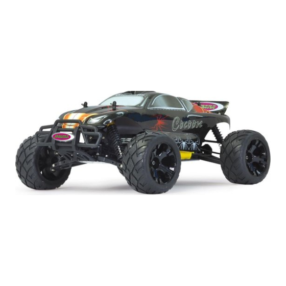
Trasmittente, modello, caricabatterie e batterie.
Per primo bisogna caricare la batteria. Collegare il caricabatterie ad una
presa 230V. Collegare il caricabatterie alla batteria del veicolo. In certi casi
utilizzare il cavo adattatore fornito per collegare la batteria con il caricatore. Il
tempo medio di carica della batteria è di circa 6 - 8 ore.
Inserire 8 batterie AA oppure 8 batterie ricaricabili AA nella trasmittente. In
caso del utilizzo di batterie ricaricabile, è necessario caricare questi con un
caricatore separato.
Leggere il capitolo sulla trasmittente.
Accendere la trasmittente e assicurarsi che i trim siano in posizione neutrale.
Avete acquistato un modello RTR. Vale a dire, che il modello è preimpostato
per la maggior parte per l'uso immediato. Tuttavia, è essenziale prima e dopo
ogni utilizzo, di controllare il funzionamento della parte meccanica ed elettro-
nica. Si consiglia di controllare anche tutte le parti in movimento del modello.
Mettete la batteria nel vano della batteria, a bordo del veicolo. Fare attenzione
che la batteria sia correttamente fi ssata con i 2 clip in dotazione e che la
batteria non abbia un gioco eccessivo nel vano appropriato. Ora collegare la
batteria con il regolatore di velocità. Tenere il modello in aria per il caso che il
motore si metta a girare a tutto gas. Ora accendere il regolatore di velocità
tramite l`interruttore ON / OFF. Posizionare il modello sul pavimento e verifi
carne il corretto funzionamento testando lo sterzo (sinistra/destra) ed il gas
(avanti/indietro) Se le ruote non puntano dritti in avanti, anche se il volante
della trasmettente è in posizione neutrale, è possibile ottenere aiuto con il trim
della trasmittente nella posizione corretta.
Trim L/R = Sterzo
Trim V/R = Avanti / Indietro
Se le ruote girano in avanti o indietro, anche se nessun comando è stato dato
attraverso il trasmettitore, poi anche l'acceleratore deve essere tagliato sul
trasmettitore. Vi incoraggio ad attivare il ricevitore integrato in unità fail-safe.
Al momento della consegna è spento.
Se le ruote girano in avanti o indietro, senza toccare lo stick del gas, è neces-
sario impostare il trim del gas nella giusta posizione. Consigliamo di attivare
il Fail Safe, integrato nel regolatore di velocità. Il Fail Safe è disattivato in
stato di consegna del prodotto. Per attivare il Fail Safe, leggere attentamente
il capitolo Fail Safe. Attivazione Fail Safe: Accertarsi che lo stick del gas
sia in posizione neutrale. Premere il tasto Fail Safe sulla ricevente finche
lampeggia il LED. Dopo il lampeggiamento del LED, lasciare il pulsante.
Ora si può fare la prima unità di prova. Se questa è la tua prima auto rc, si
consiglia di guidare su una pista piccola per familiarizzare con il controllo del
veicolo e i comandi del trasmettitore.
Attenzione!
Il veicolo è dotato di una Pivot sospensione anteriore. Questa ha una serie
di vantaggi. E ‚molto robusta e la manutenzione e´molto facile. Questo è im-
postato in fabbrica in modo che la carreggiata non permette agli cardani di
saltare fuori. Come con qualsiasi modello, dopo l´inizio dell'uso si rallentano
di qualche millimetro sia la sospensione sia i bulloni. Questo gioco minimo,
po' abbastare sotto massimo sforzo per fare saltare fuori i cardani. Pertanto
è necessario per assicurarsi prima di ogni uso che tutte le viti, dadi, giochi
ecc., sono fissate correttamente. La vita esterna in plastica 505080 serva
per fissare il fuso a snodo sulla vite a sfera. Questo non deve essere serrata
troppo forte. In caso contrario, lo sterzo non si muove liberamente e la guida
può essere influenzata negativamente.
IT - Trasmittente 2,4 GHz 2CH | GB - Transmitter 2,4 GHz 2CH
IT - Controlli
Vista laterale destra
1. Scatola di programmazione
2. Volante
1
2
3. Leva del gas
4. Vano Batterie
3
4
Con una sincronia di pulsanti, interruttori e display LCD, la trasmettente, può essere programmata rapidamente e con
facilità. Tutti i canali possono essere trimmati, inoltre è possibile invertire la direzione. In più, vi sono a disposizione le
funzioni, Dual-Rate, EXPO e ABS. Una LED indica lo stato di carica della alimentazione del trasmittente.
Vista laterale sinistra
F. Presa di carica
F
G
G. Collegamento per cavo
Simulatore
Se si carica attraverso una pre-
sa, si prega di aprire il coperchio
della batteria. Viene usato per il
raffreddamento.
IT -
Avvertenza sulle batterie:
Non ricaricabili!
Non aprire!
Non gettare nel fuoco!
2
GB - Getting Started
Make sure that all parts from the box content are included. Transmitter, Car,
Charger, battery pack.
The battery pack has to be charged before use. Plug the charger into a 230V
outlet. Connect the charger to the battery. If the plug of the charger and batte-
ry do not match, then you will find a connection lead in your box. The average
charging time of the empty battery is about 6-8 hours.
Place 8 pieces of AA batteries into the transmitter. If rechargebale, please also
make sure these are fully charged.
Read the chapter for usage of the transmitter and its controls carefully.
Turn the radio off and make sure all the trim buttons on the transmitter are in
neutral position. You have purchased a RTR model, which means it should be
ready for immediate use after charging all batteries. You need to check the
car, electronics and all plastic parts after each use to make sure no parts are
damaged. Also all the moving parts must be checked for their clearance, bolts
and screws that they are tight. Now put the battery into the battery holder in
the vehicle. Make sure that the battery holder is secured properly with the 2
included clips for the battery holder. Now connect the battery to the speed
control in the model. Keep the car in the air in case that the motor turns at full
power. Switch the speed control on the On / Off switch. Set the model on the
ground and test it for proper functioning. Steering right/ left, throttle/ brake,
forward and backward. If the wheels do not point straight forward even though
the steering wheel on the transmitter is in neutral, you can adjust it with the
trim button on the transmitter.
Trim L/R = steering
Trim V/R = forward/backward
Should the wheels rotate forward or backward, even though no command
was given through the transmitter, then also the throttle needs to be trimmed
on the transmitter.
We encourage you now to activate your receiver's built-in Failsafe unit. On
delivery it is turned off. Leave the throttle lever in neutral position (see
chapter Fail Safe). Press the fail-safe button on the receiver until it flashes
and let go to activate. Check this principle in an electric vehicle only in
the neutral position of the throttle, because otherwise the model
goes into the previously programmed throttle position in a loss of the
transmitter signal.
Now you can make the first test drive. If this is your first rc car, we recommend
to drive it on a small test track to familiarise yourself with the control of the
vehicle and the controls of the transmitter.
Attention!
Your vehicle has a pivot front suspension. This has a number of advantages.
It is very robust and easy to maintain. The set-up of the car has been done so
the drive shaft will not pop out. As with any model, screws and bolts can losen
during break-in of the car. This can result in tolerance of the drive shaft. The
drive shaft can then pop out if high pressure is applied. The inner ball screw
(item No.: 505081) will enable you to adjust the tolerance resulting in fine
adjustments of the track width. For best results when setting up the pivot ball
for the first time, please always adjust the upper and lower pivot in the same
way. Fasten as far as the pivot can still be pulled up and down easyly but not
as far that it will pop out if you give full steering angle. The outer plastic socket
screw (item No.: 505080) is only used for securing of the steering knuckle.
This should not be too tight, otherwise the steering is not smooth and the
handling can be adversely affected.
GB - Controls
Side View
1.
Programming Box
2.
Steering Wheel
3.
Throttle Lever
4.
Battery Hatch
Rear Side
F. Charge Socket
G. Simulator Cable Socket
If charging the batteries via the
charging
socket,
the
hatch cover should be removed
to ensure sufficient cooling.
GB -
Battery warning:
Do not recharge!
Do not open!
Do not dispose of in fire!
6
7
8
9
Thanks to the logical and well thought out lay-out of the Programming Panel and the positioning of the switches
and LEDs the transmitter can be quickly and simply programmed. Both channels can be trimmed and the direction
changed. Furthermore the transmitter is equipped with a Dual Rate system and a red LED indicates the state of
the battery charge.
2,4 GHz
Antenna
battery
Antenna
Empfänger/Receiver
Vers. 053240
Caricatore/Charger
Batteria/Battery
Batteria/Battery
Cavo di riduzione
Charging adapter
Batteria/Battery
Regolatore/ESC
Lipo- Modus
ON/OFF
ON/OFF
Pulsante ON/OFF
Attacco per la motore
On/Off switch
Motor connector
Attacco per la batteria
Battery connector
Cavo di allacciamento
del regolatore
Signal wire
Attacco per la motore
Motor connector
50 5080
50 5081
07 9996
Settore di programmazione
A
6.
Direzione Reverse
B
7.
Power LED
C
8.
Direzione -Trim
D
9.
Interruttore on /off
E
A.
Gas Reverse
B.
Power Check
C.
Pulsante collegamento
Binde
D.
Dual-Rate
E.
Gas Trim
Vers. 053241
Caricatore/Charger
L/R V/R
Trim
ON/OFF
50 5079
Programming Panel
6.
Steering Reverse
7.
Power LED
8.
Steering Trim
9.
ON/OFF Switch
A.
Throttle Reverse
B.
Power Check
C.
Binding Button
D.
Dual-Rate
E.
Throttle Trim
Collegare
l'antenna
verticale 2,4 GHz, come
illustrato nella
figura adiacente. Non si
può, tuttavia, montare
l'antenna su
oggetti metallici, il raggio
d'azione si ridurrebbe
notevolmente.
Mount
the
2.4
GHz
antenna
vertically
as
shown in the diagram.
Do not allow any metal
object to come into con-
tact with the antenna or
to shield it as this will
reduce the range.