Gantner GAT SLA-SLR Mounting Kit Manuel rapide - Page 3
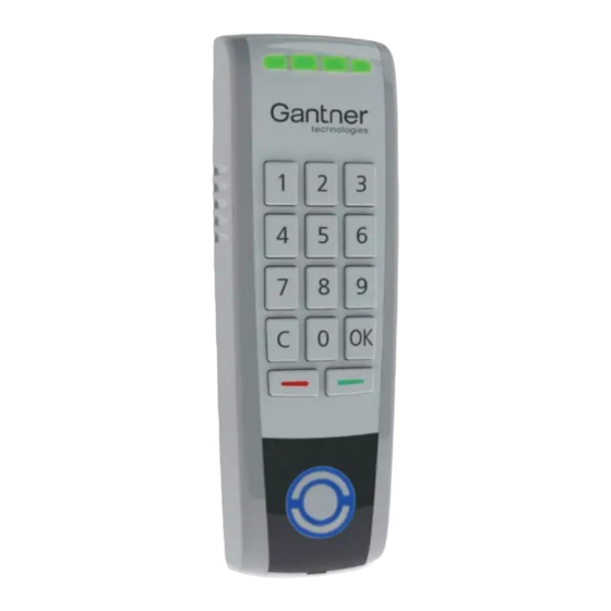
Parcourez en ligne ou téléchargez le pdf Manuel rapide pour {nom_de_la_catégorie} Gantner GAT SLA-SLR Mounting Kit. Gantner GAT SLA-SLR Mounting Kit 7 pages. Reader for access control

DE
EN
FR
DE
EN
FR
weiß
DE
EN
FR
Installation
Sicherheitshinweise
- Die Installation und Wartung dieses Gerätes dürfen nur durch
geschultes, fachkundiges Personal erfolgen.
-
Die geltenden Sicherheits- und Unfallverhütungsvorschriften sind
zu beachten.
- Schutzeinrichtungen dürfen nicht entfernt werden.
- Beachten Sie die im Datenblatt angegebenen technischen Daten
des Geräts.
- Vor Arbeiten am Gerät oder Montage/Demontage muss das Gerät
spannungsfrei geschaltet werden.
DE
EN
FR
DE
EN
FR
Funk-HF-Exposition
weiß
DE
EN
FR
Die Benutzer müssen einen Abstand von mindestens 20 cm zum GAT SLR 73xx
einhalten, außer während der Identifizierungs- und Bedienprozesse am Leser (z.
B. Eingabe des PIN-Codes).
EN
FR
EN
FR
Exposition radio RF
weiß
EN
FR
Les utilisateurs doivent se tenir à une distance d'au moins 20 cm du GAT SLR
73xx, sauf pendant les processus d'identification et d'exploitation sur le lecteur
(par ex. Saisie du code PIN).
Das Geräterückteil des GAT SLR 73xx wird mit Schrauben auf einem flachen
Unter grund (z.B. Betonwand) montiert.
Empfohlene Montagehöhe: Gerätemitte 1,3 m
Notwendige Abmessungen für die Montage
1 ...... LED Statusanzeige
2 ...... Beleuchtetes, kreisförmiges Lesefeld
3 ...... Befestigungslöcher
4 ...... Öffnung
5 ...... Geräteunterteil
6 ...... Unterputz-Kabelzuführung
7 ...... Anschlussklemmen
8 ...... Klemmenabdeckung
9 ...... Dichtungskappe
Montageschritte
ACHTUNG! Elektrischer Schlag. Der Anschluss muss im span-
nungslosen Zustand erfolgen.
•
Schließen Sie die Kabel laut elektrischem Anschlussplan auf Seite 5 an.
•
Die Kabelzuführung erfolgt Unterputz (6). Achten Sie darauf, dass der
Kabelauslass in der Wand nach Montage des GAT SLR 73xx nicht zu sehen ist.
•
Nach Anschluss der Kabel die Kunststoff-Abdeckung (8) über den Klemmen
fest aufstecken (Schutz vor Schmutz und Feuchtigkeit).
•
Das Gehäuseunterteil mit zwei Befestigungsschrauben (3) an schrauben. Die
Schrauben und Dübel sind entsprechend der Art des Unter grunds zu wählen,
so dass der GAT SLR 73xx sicher hält.
HINWEIS! Verwenden Sie keine Senkkopfschrauben.
•
Wird der GAT SLR 7307 oder 7317 im Außenbereich montiert, muss die
Dichtungskappe (9) abgetrennt und zum Schutz gegen Schmutz und
Feuchtigkeit auf die Öffnung (4) gesteckt werden.
VB_GAT-SLR73xx--DE+EN_23
Gültig ab 5. Februar 2021
Technische Änderungen vorbehalten!
Seite 3
Safety Instructions
DE
EN
FR
DE
EN
FR
FR Exposer Statement
DE
EN
FR
Die Benutzer müssen einen Abstand von mindestens 20 cm zum GAT SLR 73xx
einhalten, außer während der Identifizierungs- und Bedienprozesse am Leser (z.
B. Eingabe des PIN-Codes).
DE
EN
FR
DE
EN
FR
Exposition radio RF
weiß
DE
EN
FR
Les utilisateurs doivent se tenir à une distance d'au moins 20 cm du GAT SLR
73xx, sauf pendant les processus d'identification et d'exploitation sur le lecteur
(par ex. Saisie du code PIN).
The rear part of the GAT SLR 73xx is attached to a flat surface (e.g., concrete
wall) using screws.
Recommended mounting height: 1.3 m to middle of device.
1
3
5
6
3
4
2
44,0 mm
•
Complete the electrical connections according to the instructions on page 5.
•
Ensure that the outlet for the flush-mounted cable (6) is covered after mounting
the GAT SLR 73xx.
•
After completing the electrical connections, press the cover (8) securely onto
the connection terminal to protect against dirt and moisture.
•
Attach the device rear part to the wall using two screws (3). Use the correct
type of screws and dowels according to the wall material and ensure that the
GAT SLR 73xx is attached securely.
NOTE! Do not use countersunk screws.
•
If the GAT SLR 7307 or 7317 is installed outside, cut the sealing cap (9) off
from the terminal cover and plug it into the opening (4) to protect against dirt
and moisture.
GANTNER Electronic GmbH
www.gantner.com/locations
- The installation and maintenance of this device must be performed
by trained, qualified personnel.
- All applicable safety and accident prevention regulations must be
observed.
- Safety devices must not be removed.
- Please observe the technical data of the device specified in this
datasheet.
- The device must be disconnected from the power supply prior to
installation, assembly, or disassemly.
weiß
Required measurements for installation
8
7
9
5
22,2 mm
CAUTION! Electrical shock. The electrical connections must be
made in a powerless state.
Technical data subject to modification without notice!
DE
EN
FR
DE
EN
FR
DE
EN
FR
Installation
1 ......LED status display
2 ......Illuminated scan field
3 ......Mounting holes
4 ......Opening
5 ......Device rear part
6 ......Flush-mounted cable
7 ......Connection terminals
8 ......Connection terminal cover
9 ......Sealing cap
Installation instructions
VB_GAT-SLR73xx--DE+EN_23
Valid as of 5
February 2021
th
Page 3
