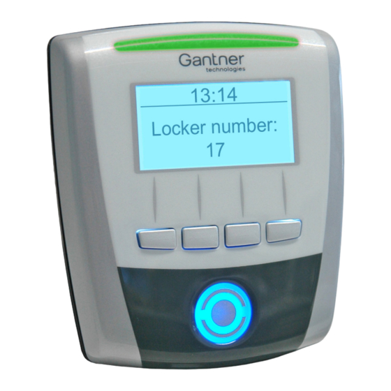
Gantner GAT Info 6100 F Instructions d'installation - Page 3
Parcourez en ligne ou téléchargez le pdf Instructions d'installation pour {nom_de_la_catégorie} Gantner GAT Info 6100 F. Gantner GAT Info 6100 F 4 pages. Information terminal

Installation instructions
The rear part of the device attaches to a flat surface (e.g., concrete wall)
using screws. If attaching to an uneven surface, the rear part must not be
distorted as this prevents the correct connection of the device front part.
Recommended mounting height: 1.3 m to middle of device.
69 mm (2.72´´)
60 mm (2.36´´)
7
6
7
1
6
6
7
2
13 mm (0.51´´)
1. Flush-mounted cabling access
2. Surface-mounted cabling access
3. Back box
4. Device rear part
5. Conduit for surface-mounted cabling
6. Mounting hole for back box
7. Mounting hole
Installation
• The cabling can be flush mounted (1) or surface mounted (2).
• For surface-mounted cabling, ensure the cabling can still be inserted
once the device rear part has been mounted. Otherwise, run the
cabling through the cable lead-ins prior to securing.
• For flush-mounted cabling, ensure that the outlet for the cable is
covered after mounting the rear part.
• When mounting the device in a standard back box, use the three
mounting holes marked 6 in the diagram. When mounting the device to
a wall, use the three mounting holes marked 7 in the diagram.
• Attach the device rear part to the wall using three screws. Use the
correct type of screws and dowels according to the wall material and
ensure that the rear part is attached securely.
• Complete the electrical connections according to the instructions on
page 4.
CAUTION! The electrical connections must be made in a
powerless state.
www.gantner.com
Attaching the device front part
After installing the device rear part and completing the electrical
connections, the device front part attaches to the rear part as follows.
• Ensure that the socket in the device rear part (circled below) is free
from dust and moisture.
4
3
5
NOTICE! If cleaning is required, do not use any aggressive detergents
and take care not to damage the contacts. Only clean the device in a
powerless state.
• Ensure that the cabling is stored safely and will not be damaged when
the front part is attached.
• Plug the connection cable into the socket on the device rear part.
• Hook the top of the front part into the top of the rear part.
• Swing the bottom of the front part forward until it clicks into place in
the rear part.
Removing the device front part
The device can only be opened using the supplied special tool (Part No.:
581683).
• Use the special tool to release the two catches on the bottom of the
device in succession.
• Carefully swing the device front part forward.
Valid from July 1
1.
2.
, 2016 • Technical data subject to modification without notice!
st
DB_GAT-INFO6100--EN_12.indd • Part No.: 860380
1.
3.
3
