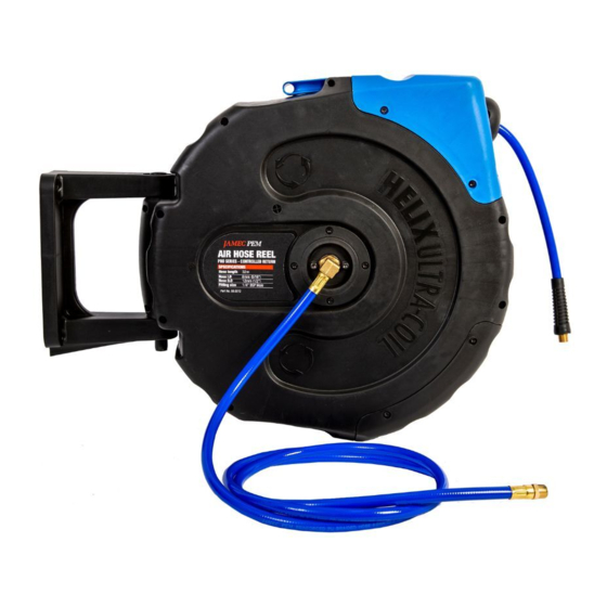
JAMEC PEM 58.4023 Manuel d'utilisation - Page 3
Parcourez en ligne ou téléchargez le pdf Manuel d'utilisation pour {nom_de_la_catégorie} JAMEC PEM 58.4023. JAMEC PEM 58.4023 8 pages. 8 metre air and water hose reel
Également pour JAMEC PEM 58.4023 : Mode d'emploi (2 pages)

INSTALLATION
The Jamec Pem PRO SERIES Reel can be
mounted in a horizontal or vertical position.
1. Chose a location that is near to the water
source or compressed air source.
2. For large areas, place the hose reel at the
centre of the work area.
3. When mounting the hose reel vertically,
ensure there is adequate clearance under
the reel to prevent injury or damage.
4. Mounting bracket must be installed on
a flat surface.
Note: It is recommended to install the
mounting bracket 0.8 metre (minimum)
above the floor level.
0.8 metre min.
OPERATION
1. Slowly pull out the hose to the required
length. A 'clicking' noise will be heard every
revolution of the inner drum. To lock the reel,
allow the hose to retract slowly after hearing
the second or third 'click'.
2. To release the hose, pull out the hose until
the 'clicking' noise stops, and then allow the
hose to slowly retract while guiding the hose
back into the hose reel. The self layering
mechanism will coil the hose back onto the
inner drum.
5. Drill 4 x M8 holes to
match the holes located
in the Mounting Bracket.
(Fig. 1)
6. Connect the hose reel
to the Mounting Bracket
with the Pivot Pin.
(Fig. 2)
Note: For fixed in-line
position, fit the locking
plate onto the Mounting
Bracket prior to inserting
the pivot pin. (Fig. 3)
7. Connect the inlet
leader hose to the
source using the
fittings supplied.
Note: Apply thread sealing
tape to all air line and air
hose fittings.
3. To avoid injury and damage, always hold
the hose while it is retracting.
IMPORTANT:
If the hose becomes tangled and will not
retract - slowly pull out the hose past the
tangled section and then allow the hose to
slowly retract while guiding it back into the
hose reel.
Always ensure the hose is clean and
not twisted.
Fig. 1 Mounting Bracket
Fig. 2 Pivot Pin
Fig. 3 Locking Plate
