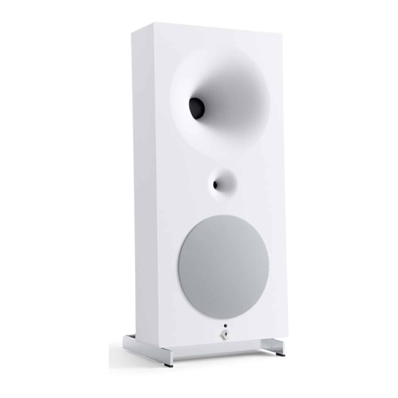
Avantgarde ZERO 1 Manuel de l'utilisateur - Page 7
Parcourez en ligne ou téléchargez le pdf Manuel de l'utilisateur pour {nom_de_la_catégorie} Avantgarde ZERO 1. Avantgarde ZERO 1 13 pages.

MASTER – AUFSICHT / TOP VIEW
DIGITAL INPUTS
USB
OPT
DIGITAL INPUTS
USB
OPT
SPDIF2
SPDIF1
AES/EBU
SPDIF2
SPDIF1
AES/EBU
MASTER – SEITENANSICHT / SIDE VIEW
❶
❸
LEFT
USB
2 x SPDIF
XLR ANALOG
❷
❹
AES/EBU
TOSLINK OPT.
SLAVE – SEITENANSICHT / SIDE VIEW
12
ANALOG INPUT
POWER
BALANCED
(OPTIONAL)
ANALOG INPUT
POWER
GAIN
BALANCED
(OPTIONAL)
LEFT
RIGHT
WIRE LINK
GAIN
LEFT
RIGHT
WIRE LINK
❿
DIP–SWITCH
BASS RESPONSE
❺
❻
RIGHT
❼
WIRE–LINK
❽
(optional)
ON/OFF
SWITCH
BEDIENUNG
DIGITALE EINGÄNGE
• Die digitalen Musikquellen mit den digitalen Eingängen
(USB ❶, TOSLINK ❷, SPDIF ❸ und/oder AES/EBU ❹)
des Master Lautsprechers (siehe Abb. links) verbinden.
• Der Lautsprecher ist nicht mit einem eingebauten WLAN
Empfänger ausgerüstet. Zur Integration des Lautsprechers
in einem Funknetz, eine externe WLAN Schnittstelle (z.B.
AirPort Express) über ein optisches TOSLINK Digitalkabel
mit dem TOSLINK ❷ Eingang des Lautsprechers verbinden.
Es können alle digitalen Eingänge gleichzeitig belegt
werden. Das Aktivieren des entsprechenden Eingangs er-
folgt mit der Fernbedienung.
ANALOGER EINGANG (OPTIONAL)
• Optional ist ein analoger Eingang ❺-❻ erhältlich. Dieser
hochwertige Analog-Digital Konverter ist nicht im Standard
Lieferumfang enthalten, kann aber jederzeit vom authori-
❾
sierten Service Personal nachgerüstet werden.
MAINS
WIRE–LINK ZWISCHEN MASTER UND SLAVE
INPUT
• Master und Slave Lautsprecher sind untereinander über
Funk oder optional einer Kabelverbindung (Wire–Link ❼)
verbunden. Hierfür Ethernet Kabel (CAT.5/5e/6 LAN Kabel
mit Standard 8P8C/RJ45 Stecker; 100 Ohm) verwenden.
Bei Verwendung des Wire–Links schaltet sich das Funk–
Modul automatisch aus.
Die Wire–Link ❼ Buchse NICHT zum Anschluss des
Lautsprechers an ein Ethernet Datennetz verwenden!
OPERATION
DIGITAL INPUTS
• Connect the digital music sources with the digital inputs
(USB ❶, TOSLINK ❷, SPDIF ❸ and/or AES/EBU ❹) of the
master speaker (see graphics left).
• The speaker is not equipped with an internal WLAN re-
ceiver. Connect an external WLAN interface (ex. AirPort
Express) through an optical TOSLINK cable with the
TOSLINK ❷ input of the master speaker, to integrate the
speaker in a WLAN environment.
All digital inputs can be connected at a time. The activa-
tion of the inputs is done with the remote control.
ANALOG INPUT (OPTIONAL)
PIN 1 = GND
PIN 2 = hot
PIN 3 = cold
• An analog input ❺-❻ is available an an option. This high
quality analog-digital converter is not included in the stan-
dard version of the system. The analog-digital converter can
be retrofitted anytime by authorized service staff.
WIRE–LINK BETWEEN MASTER AND SLAVE
• Master and slave speaker communicate with each other
via radio signal or alternatively via a Wire–Link ❼. For the
Wire–Link ❼ connection use an Ethernet Kabel (CAT.5/5e/6
LAN cable with standard 8P8C/RJ45 plug; 100 Ohm). The
radio module will automatically switch–off, when the Wire–
Link is connected.
Do NOT use the Wire–Link ❼ socket to connect the
speaker to an Ethernet computer network.
PIN 1 = GND
PIN 2 = hot
PIN 3 = cold
13
