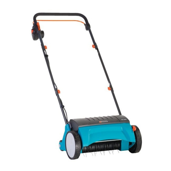
Gardena ES 500 Manuel de l'opérateur - Page 5
Parcourez en ligne ou téléchargez le pdf Manuel de l'opérateur pour {nom_de_la_catégorie} Gardena ES 500. Gardena ES 500 15 pages. Electric lawn rake
Également pour Gardena ES 500 : Manuel d'utilisation (12 pages), Manuel d'utilisation (9 pages), Manuel de l'opérateur (15 pages), Manuel de l'opérateur (15 pages), Manuel de l'opérateur (9 pages), Manuel de l'opérateur (9 pages)

4. Assembly
Assembling the handle:
8
4
c
2
5
v First of all, mow your lawn to the length you require.
We particularly recommend this if the grass has grown tall
(e.g. while you were away on holiday).
Recommendation: the shorter you mow your lawn, the easier
it is to aerate, thus lessening the strain on the Electric Lawn
Rake and increasing the lifetime of the aerator cylinder.
Remaining in one spot too long, or aerating if the ground is wet or
too dry can damage the grass.
v For good results, guide the Electric Lawn Rake at an
appropriate speed in strips as straight as possible across
your lawn.
To avoid leaving any gaps during aerating, the strips should
touch.
v Always guide the Electric Lawn Rake at an even speed
depending on the type of ground.
v When working on inclines always stand diagonally to the
incline in a sturdy, safe stance. Do not work on extremely
steep slopes.
Danger of tripping!
To prevent tripping take particular care when moving
backwards and when pulling the Electric Lawn Rake.
When aerating areas of very mossy lawn we recommend resowing
the lawn after aerating. This helps the areas of lawn which were
replaced by moss to regenerate more quickly.
v Do not place the connecting cable
1. Insert the two lower sections of the upright
7
with the round hole) in the mountings in the motor casing
and secure with the crosshead screws
3
2. Insert the two locking bolts
in the two central sections
lower sections of the upright
3. Screw the upper part of the upright with starting handle
1
the central sections of the upright
bolts
1
This completes the assembly of the handle.
6
Warning: Fit the upper section of the upright with starting
handle
cable
8
9
(see fig.).
4. Attach connection cable
clips
c
during assembly.
1
2
5
and the wing nuts
.
4
in such a way that the plug
3
is on the right side (in direction of movement)
to the handle with the two cable
8
.
under strain
8
(with the end
5
.
9
from outside through the holes
of the upright and secure to the
with two wing nuts
4
with two more locking
2
with the power
7
6
.
to
3
15
