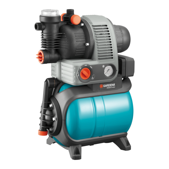
Gardena 4000/5 eco Manuel de l'opérateur - Page 5
Parcourez en ligne ou téléchargez le pdf Manuel de l'opérateur pour {nom_de_la_catégorie} Gardena 4000/5 eco. Gardena 4000/5 eco 10 pages. Pressure tank unit
Également pour Gardena 4000/5 eco : Manuel d'utilisation (18 pages), Manuel d'utilisation (17 pages), Manuel de l'opérateur (10 pages), Manuel d'utilisation (17 pages)
Alternatively, spring mounted feet (Art. 1753-00.901.00) for low vibration
and quiet running are available as accessories via the GARDENA Service.
Install the pressure tank unit so that there is room to place a suitably sized
drainage tray under the drain screw
drained.
If possible, install the unit higher than the surface of the water to be
pumped. If this is not possible, install a vacuum-resistant valve between
the unit and the suction hose, for example for cleaning the integrated filter.
If the pump is permanently installed indoors for domestic water supply,
the Pressure Tank Unit should not be connected to the domestic water
pipework with rigid pipes but with flexible tubing, to reduce noise and to
avoid damage to the pump caused by pressure blows.
If the system is being installed permanently, please fit suitable valves on
both the intake and delivery sides. This is important e. g. for maintenance
and cleaning work or if the system is being shut down.
The connection pieces on the intake and delivery sides may only
be tightened by hand.
Connect the hose to the suction side [ Fig. I2 ]:
A vacuum-tight suction hose must be used e. g.:
– GARDENA Suction Unit Art. no. 1411 / 1418 / 1412 or
– GARDENA Bore Hole Suction Hose Art. no. 1729.
Do not use any water hose snap connection system components on the
intake side!
v Connect the suction hose
5
connection
6
of the pump.
5
Connect the suction hoses
without a threaded connector via a connec-
tion piece (e.g. Art. no. 1723/1724)
and screw in place so that they are airtight.
To reduce the pump repriming time, we recommend using a suction hose
with backflow preventer, which prevents the suction hose emptying auto-
matically when the Pressure Tank Unit is switched off.
For suction heights exceeding 4 m also secure the suction hose
(e. g. by fastening it to a wooden post) to relieve the pump of the weight
of the suction hose.
If very fine dirt is present in the pumping medium, we recommend the
use of a GARDENA Pump Preliminary Filter Art. no. 1730 / 1731.
Connect hose to the output side [ Fig. I3 ]:
Note:
Use pressure-tight GARDENA hoses, 19 mm (3/4") in diameter, in
connection with the GARDENA Quick-Release Threaded Connector with
33.3 mm (G1) internal thread, Art. no. 7109, and the GARDENA Suction
and High Pressure Connector, Art. no. 7120, for 19 mm (3/4") hoses
and a GARDENA Hose Clip, Art. no. 7192.
Under no circumstances use these hoses on the suction side.
v Connect delivery hose
7
to the delivery side connection
v Tip: If permanent pipes are installed, they must be laid at an ascending
angle in order to allow the water to flow back into
the pump on the pressure side.
3. OPERATION
Starting the Pressure Tank Unit [ Fig. O1 / O2 / O3 ]:
DANGER! Electric shock!
v Before filling the pump, unplug the equipment from the
mains.
CAUTION! Pump running dry!
v Fill the pump to the overflow (approx. 2 to 3 l) with water each
time before the pump is switched on, so it does not run dry.
0
1. Unscrew the cover
of the filter chamber by hand.
2. Turn the rotary switch
q
to FILL.
The integrated non-return valve will open.
w
3. Open the air bleed
.
4. Open any valves in the delivery line (watering accessories, water stop,
etc.) and drain off any residual water in the delivery hose so that the air
can escape during filling and priming.
5. Slowly pour pumping medium (approx. 2 to 3 l) through the filler
e
neck
until water emerges from the air bleed
6. Screw the filter chamber cover
stops.
8
3
to allow the unit or system to be
with the intake side
4
with the intake side connection
5
8
w
.
0
closed again, turning by hand until it
7. Close venting
w
and turn rotary switch
8. Insert the mains plug into a 230 V mains socket.
CAUTION! The pump will start immediately!
Once the maximum pressure is reached the pump will switch off automati-
cally. When the pressure falls below the minimum value due to water being
drawn off, the pump will switch on again automatically.
The maximum self-priming head of 8 m is only achieved if the pump is fil-
led until it overflows from the filler connection
held high enough during self-priming so that no water can escape from
the pump via the delivery hose. It is not necessary to hold up the delivery
hose if filled suction hoses with backflow preventer are used.
ECO switch [ Fig. O4 ]:
In order to save energy (up to 15 %), the cut-out pressure on the pump
can, depending on the individual application, be regulated between ECO
and MAX (the pressure difference between ECO and MAX totals
approx. 1 bar).
v Turn the ECO rotary switch
Note on the use of sprinklers:
Depending on the flow rate of the sprinkler, an uneven watering pattern
may occur through the pump being switched on and off automatically.
4. STORAGE
To put into storage [ Fig. S1 / O1 ]:
If there is a risk of frost, the Pressure Tank Unit must be emptied
and stored where it will not become frozen. The product must
be stored away from children.
1. Unplug the mains connection for the pump.
2. Turn the rotary switch
3. Open the delivery side consumer.
4. Unscrew the end cap
5. Store the pressure tank unit in a dry, frost-free place.
Disposal:
(in accordance with RL2012/19/EC)
The product must not be disposed of to normal household waste.
It must be disposed of in line with local environmental regulations.
IMPORTANT!
v Dispose of the product through or via your municipal recycling
collection centre.
5. MAINTENANCE
DANGER! Electric shock!
.
v Pull out mains plug before undertaking any maintenance.
Clean suction filter [ Fig. M1 / O3 / M2 ]:
1. Turn the rotary switch
2. If necessary, close all the shut-off devices on the intake side.
3. Unscrew and remove cover
4. Draw out filter unit
5. Hold beaker
z
firmly, turn filter
(bayonet fitting).
6. Clean beaker
z
under running water and clean the filter
a soft brush.
7. Refit filter again in reverse order.
Cleaning the check valve [ Fig. M3 / O1 ]:
1. Turn the rotary switch
2. If necessary, close all valves on the intake side.
3. Open all pressure side outlets, so that the pressure side is
depressurised.
4. Unscrew the end cap
"To put into storage").
o
5. Undo screw
and slide the clip
the bearing groove.
6. Screw out the cover
tool).
7. Remove the valve body
q
to RUN.
e
and the delivery hose is
r
to the required position.
q
to FILL.
9
and drain off the water.
q
to RUN.
0
of the filter chamber.
z u
vertically upwards.
u
anti-clockwise A and draw out B
q
to FILL.
9
and drain off the water (see 4. STORAGE
p
upwards 1 and to the rear 2 into
t
of the check valve (if applicable using a suitable
i
and wash it under running water.
u
e. g. with