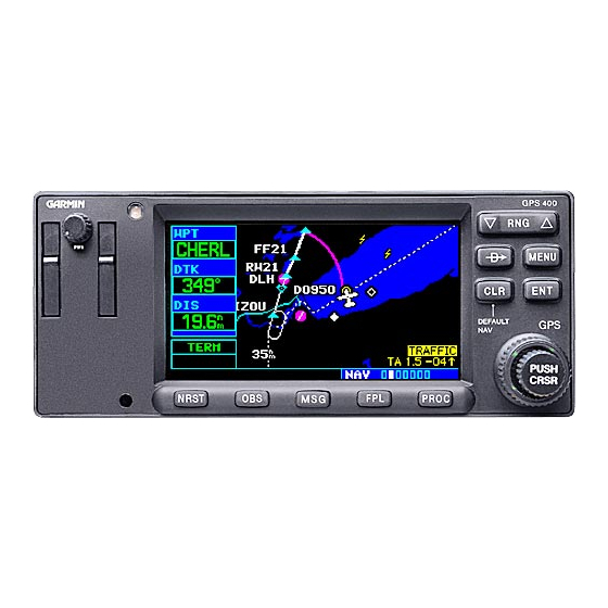
2.3 Control, Operating Information
See the Pilot's Guides or the 400W Rotorcraft STC Installation Manual for system operation and self-test
information. The 400W Rotorcraft STC Installation Manual is listed under the reference documentation in
paragraph 2.1 of this document, and the Pilot's Guides are listed in the related documents section of the
400W Rotorcraft STC Installation Manual.
2.4 Servicing Information
None. In the event of system failure, troubleshoot the 400W Series unit in accordance with Section 2.6.
2.5 Periodic Maintenance Instructions
The 400W Series units are designed to detect internal failure. A thorough self-test is executed
automatically upon application of power to the units, and built-in test is continuously executed. Detected
errors are indicated on the equipment via failure annunciations.
Maintenance of the components installed by this STC is on condition, except as noted in the following
table.
Item
Interval
400W Series
12 Months
Unit
400W Series
12 Months
Mounting Rack
Every 2000
flight hours or
400W Series
ten (10)
Mounting Rack
years,
whichever is
first
Avionics
12 Months
Cooling Fan
400W Series
Instructions for Continued Airworthiness Bell 206B
Table 1 Periodic Maintenance Inspections
Description/Procedure
Conduct a visual inspection (look for signs of wear, deterioration,
or damage to wires, backshells, or connectors) of the 400W
Series unit and wiring harnesses to ensure installation integrity:
1. Inspect the unit for security of attachment.
2. Inspect all knobs and buttons for legibility.
3. Inspect condition of wiring, routing and
attachment/clamping.
4. Inspect related antennas for proper sealing and
attachment.
5. Inspect integrity of shield terminations.
6. Inspect for signs of corrosion on equipment, racks and it's
backplates and rack mounting.
Inspect the mounting rack for any signs of excessive wear,
corrosion, or damage. Check mounting rack corners for cracks.
Check integrity of connector plate attachment to the back of
mounting rack.
Perform an electrical bonding test:
1. Remove 400W Series unit from mounting rack
2. Measure the resistance between the mounting rack and a
nearby exposed portion of aircraft metallic structure and
verify it is less than 10 milliohms.
Reinstall the 400W Series unit in the mounting rack
Conduct a visual inspection (look for signs of wear, deterioration,
or damage to wire harness and connector) of the cooling fan to
ensure installation integrity. Inspect for signs of corrosion on
equipment and mounting brackets.
190-01226-04 Rev. 2
Page 7 of 22

