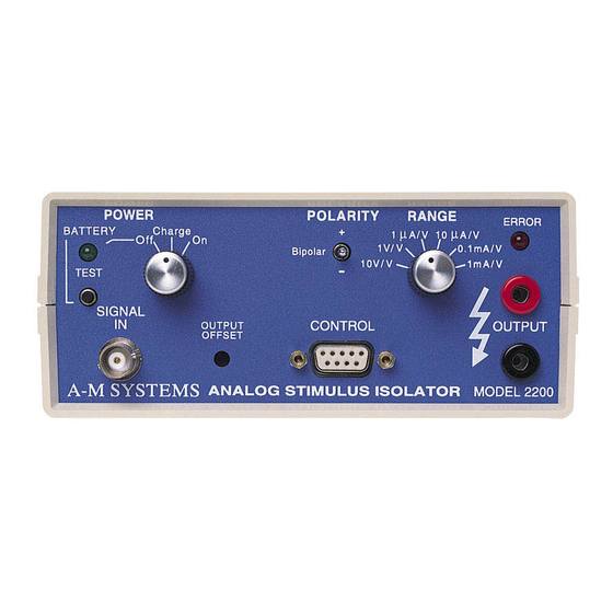
A-M Systems 2200 Manuel d'instruction - Page 13
Parcourez en ligne ou téléchargez le pdf Manuel d'instruction pour {nom_de_la_catégorie} A-M Systems 2200. A-M Systems 2200 19 pages. Analog stimulus isolator

The operation of the Model 2200 is summarized in the block diagram (see Fig. 4). The input
signal is buffered, then enabled or disabled by an analog gate. When disabled, the output
voltage at this stage is zero. A linear optoisolator system is used to couple the signal to the
isolated section. The isolated signal is amplified (and possibly converted to a current)
according to the Range setting.
The output amplifier is connected as a voltage-gain amplifier in voltage modes, with different
feedback resistances depending on the setting. In the current mode, the same amplifier is
used to fix a virtual ground within the instrument. The two currents connected to this virtual
ground are the set current, determined by the range switch and input signal amplitude; and
the load, driven by the amplifier output
With the Control Gate input signal open (disconnected), or set to a logical I by an external
signal, the signal propagates normally as described above. If the Gate is set to a logical 0, the
internal signal is connected to the input ground instead of the input signal.
Output errors are measured by sensing the output amplifier's differential input voltage. If for
any reason the amplifier fails to deliver the requested signal, a warning LED illuminates and
the Error output pin is set to a TTL-high level.
Two sets of batteries are used to power the 2200. Note that the BATTTERY tester only detects
the present state of the batteries, and does not indicate how long the charged batteries will be
able to support the load. The batteries used in the 2200 vary more from unit to unit than from
fullly-charged to nearly-discharged, making it impractical to measure the charge state. It is
recommended that you, the user, keep track of battery usage to ensure that the battery does
not become exhausted at a critical time.
A-M Systems
Theory of Operation
Figure 4. Instrument block diagram
PO BOX 850, Carlsborg, WA 98324 USA
Telephone: 800-426-1306 * 360-683-8300 * FAX: 360-683-3525
E-mail: [email protected] * Website: http://www.a-msystems.com
10
