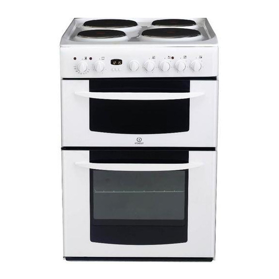
Indesit KD6E35W Manuel d'instructions pour l'installation et l'utilisation - Page 4
Parcourez en ligne ou téléchargez le pdf Manuel d'instructions pour l'installation et l'utilisation pour {nom_de_la_catégorie} Indesit KD6E35W. Indesit KD6E35W 32 pages. Free standing electric cooker

Installation
WARNING – THIS APPLIANCE MUST BE EARTHED.
MAINS CONNECTION
UK Household:
Your cooker should have been checked to ensure that the voltage corresponds with your supply
voltage, this is stated on the rating plate, which is situated on the outer rear panel.The model number
and the serial number are located on the front of the cooker, as shown on the Features page.
The cooker must be connected by a competent person such as one who is a, NICEIC registered
contractor to a suitable double-pole control unit with a minimum rating of 32A and a minimum
contact clearance of 3mm (applicable to newer properties, older properties where a 30A double
pole control unit and a minimum contact clearance of 3mm is acceptable).
The double pole control unit should be fitted adjacent to the cooker, in accordance with IEE
regulations. The control unit must be within 2 metres of but not directly above the appliance and
should be easily accessible in the event of an emergency.
The power supply cable should conform to B.S.6004 with a conductor size of 6mm
Access to the mains terminals is gained by removing the rear access cover. The mains cable must
pass through the cable clamp adjacent to the terminal block. Sufficient cable should be used to
allow the cooker to be pulled out for servicing.
Ensure that the mains cable is routed away from any brackets affixed to the rear panel and
is not trapped to the rear wall when pushing the cooker into position between cabinets.
European 3 phase Household:
Your cooker can be converted to be suitable for 3 phase European households.
Note: The conversion and connection must be done in accordance with local and national
installation requirements.
To install this appliance to 3 phase, the 'L' link pins
of the MTB need to be removed.
-
Remove the 2 link pins from L1/L2 and L2/L3
-
Then wire the 3 phase L1, L2 and L3 into
terminals L1, L2 and L3, as shown in the
diagram.
4
2
, minimum.
THE 'N' LINK PIN TO
REMAIN ON THE MTB
