DeZurik G-SERIES Manuel - Page 8

Parcourez en ligne ou téléchargez le pdf Manuel pour {nom_de_la_catégorie} DeZurik G-SERIES. DeZurik G-SERIES 8 pages. Lift, turn and reseat used on ptw & pfw tapered plug valves
Également pour DeZurik G-SERIES : Instruction (7 pages), Manuel (17 pages), Manuel (14 pages), Manuel (12 pages), Manuel (14 pages), Manuel (16 pages), Instruction (19 pages), Manuel (17 pages), Manuel d'instructions (13 pages), Manuel (9 pages)
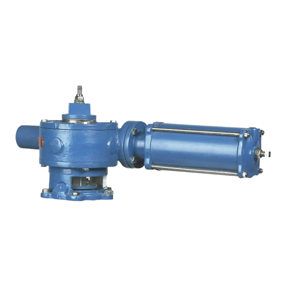
DeZurik G-SERIES Manuel
DeZURIK
MANUAL G-SERIES ACTUATORS FOR USE WITH PTW & PFW TAPERED PLUG VALVES

Changing Actuator Mounting Positions

The actuator can be mounted in 30° increments around the valve stem. The procedure to change
actuator mounting positions is dependent upon the mounting position desired. Refer to the valve
Installation Drawing for a view showing all possible mounting positions.
60°, 120°, 180°, 240° and 300° Mounting Positions
1. Remove the actuator from the valve as described in the ACTUATOR REMOVAL Section of this
Instruction.
2. Rotate the actuator to the desired position.
3. Install the actuator on the valve as described in Steps 3 thru 9 of the ACTUATOR
INSTALLATION Section of this Instruction.
90° and 270° Mounting Positions
1. Follow steps 1 thru 8 of the BEARING AND SEAL REPLACEMENT Section of this Instruction.
2. Take out the four screws fastening the actuator housing to the adaptor, then turn the housing to
the desired new position.
3. Reinstall the four screws to fasten the housing to the adaptor.
4. Follow steps 16 thru 24 of the BEARING AND SEAL REPLACEMENT Section of this
Instruction.
30°, 150°, 210° and 330° Mounting Positions
1. Follow steps 1 thru 8 of the BEARING AND SEAL REPLACEMENT Section of this Instruction.
2. Remove the screws fastening the adaptor to the adaptor plate (2" thru 4" valves) or to the valve
bonnet (5" thru 16" valves).
3. Turn the actuator and adaptor clockwise until the next set of screw holes line up, then fasten the
adaptor to the valve.
4. Take out the four screws fastening the actuator housing to the adaptor, then turn the housing to
the desired new position.
5. Reinstall the four screws to fasten the housing to the adaptor.
6. Follow steps 16 thru 24 of the BEARING AND SEAL REPLACEMENT Section of this
Instruction.
D10192
Page 8
August 2012