DeZurik G-SERIES Manuel - Page 10

Parcourez en ligne ou téléchargez le pdf Manuel pour {nom_de_la_catégorie} DeZurik G-SERIES. DeZurik G-SERIES 16 pages. Lift, turn and reseat used on ptw & pfw tapered plug valves
Également pour DeZurik G-SERIES : Instruction (7 pages), Manuel (8 pages), Manuel (17 pages), Manuel (14 pages), Manuel (12 pages), Manuel (14 pages), Instruction (19 pages), Manuel (17 pages), Manuel d'instructions (13 pages), Manuel (9 pages)
DeZurik G-SERIES Manuel
DeZURIK
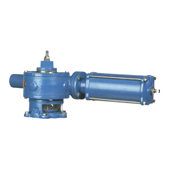
Cylinder Operated G-Series Actuator

Disassembling Actuator

When eccentric valves are mounted in a vertical pipeline, or mounted in a horizontal pipeline with the
plug stem horizontal, gravity can cause the plug to swing to a lower position in the valve body when the
actuator is removed. To avoid this problem, place the plug in the lowest position before removing the
actuator.
See Figure 6 for actuator parts identification.
1. Discontinue flow and relieve pipeline pressure and place the actuator in the open position.
Accidental operation of power actuator can cause personal injury or equipment damage.
Disconnect and lock out power to actuator before servicing.
2. Disconnect and lock out the pneumatic power to prevent accidental operation of the actuator.
Disconnect the tubing from the cylinder.
3. Remove the screws (B23), nuts (B24), lockwashers (B28) and stop cap (B29) from the actuator
housing (B1).
4. Remove the cap nut (B25), jam nut (B22) and spring washers (B21) from the end of the rack rod
(B6).
5. Remove the screws (B27) fastening the cylinder assembly to the actuator housing (B1), and
carefully remove the cylinder assembly and rack rod (B6) by sliding it away from the actuator
until the rack rod clears the actuator housing.
6. Remove the screws (B18) fastening the pointer to the gear (B3) and remove pointer.
7. Scribe corresponding lines on the cover (B2) and housing (B1) to be used for alignment during
assembly, then remove the screws (B13) fastening the cover to the housing and remove cover.
8. Remove the rack (B4) and gear (B3) from the housing (B1).
9. Remove screws (P2) and lockwashers (P3) and lift actuator assembly off valve.
10. Remove the rack bearing (B7) (if wear is noticeable) from the housing (B1).
D10455
Page 10
August 2012