Avsl Adastra DM25 Manuel de l'utilisateur - Page 3
Parcourez en ligne ou téléchargez le pdf Manuel de l'utilisateur pour {nom_de_la_catégorie} Avsl Adastra DM25. Avsl Adastra DM25 9 pages. Compact 100v mixer-amplifiers
Également pour Avsl Adastra DM25 : Manuel de l'utilisateur (9 pages)

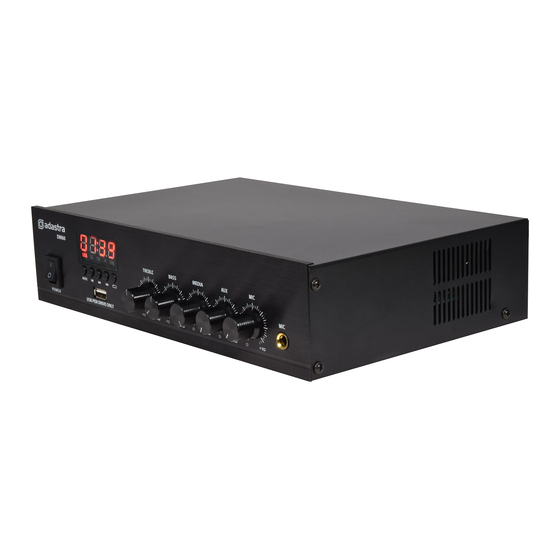
Front panel
Rear panel
Connection and setup
Connect the rear IEC inlet (17) to the mains using the supplied mains lead (or an equivalent
approved type). Ensure that the mains voltage is correct and that the mains outlet is switched on.
Connect any line level audio inputs to the Aux input (12) on the rear panel using RCA leads.
Connect a microphone (if required) to the front panel jack input (10).
Further amplifiers can be connected from the rear Out RCA sockets (11).
The DM series amplifiers can be used either with 100V line or standard low impedance speakers.
These 2 configurations cannot be used together, so it is important to decide which method will be
used at the start.
Speaker connections are provided as spring terminals on the rear panel (13, 14, 15)
Wiring is described for each type of speaker system on the following page.
Next to the speaker connections is a spring terminal for FM Antenna (16)
This should be connected to the core of an antenna cable for good FM radio reception (if required)
NOTE: Do not connect a speaker output to the antenna by mistake. This may carry high voltage.
1.
Power on/off switch
2.
Media player display
3.
USB media port
4.
Media player mode & transport controls
5.
Treble EQ
6.
Bass EQ
7.
Media player level
8.
Auxiliary input level
9.
Microphone level
10. Microphone input jack
11. Aux output connectors (RCA)
12. Aux input connectors (RCA)
13. COM speaker terminal
14. 4-16Ω speaker terminal
15. 100V speaker terminal
16. FM antenna connection
17. IEC mains inlet & fuse holder
DM series mixer-amplifiers User Manual
