AVT 1916 Manuel de démarrage rapide - Page 2
Parcourez en ligne ou téléchargez le pdf Manuel de démarrage rapide pour {nom_de_la_catégorie} AVT 1916. AVT 1916 4 pages. Configurable 4-channel switch

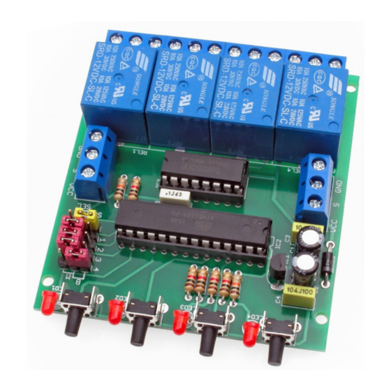
Schematic diagram of the switch is shown in Figure 2.
Start by soldering resistors and other small
components onto the board and finish by fitting
electrolytic capacitors, screw connectors and relays. A
properly assembled circuit, once the configuration
jumpers have been properly set, is immediately ready
D1
1N4007
VCC
C1
GND
100uF
+5V
R1
10k
IC2
1
PC6(/RESET)
22
GND
21
AREF
20
AVCC
PC4(ADC4/SDA)
9
PB6(XTAL1/TOSC1)
10
PB7(XTAL2/TOSC2)
8
GND
7
VCC
C5
100nF
GND
GND
Fig. 1 Schematic diagram
Fig. 2 Arrangement of components on the PCB
+12V
+5V
IC1
78L05
3
VO 1
VI
GND
2
C3
C4
100nF
100nF
GND
23
S2
PC0(ADC0)
24
LED3
PC1(ADC1)
25
S3
PC2(ADC2)
26
LED4
PC3(ADC3)
27
S4
28
LED5
PC5(ADC5/SCL)
2
P4
PD0(RXD)
3
P3
PD1(TXD)
4
IR
PD2(INT0)
5
P2
PD3(INT1)
6
P1
PD4(XCK/T0)
11
PK2
PD5(T1)
12
PK1
PD6(AIN0)
13
SEL
PD7(AIN1)
14
SYN
PB0(ICP)
15
PK3
PB1(OC1A)
16
PK4
PB2(SS/OC1B)
17
LED1
PB3(MOSI/OC2)
18
S1
PB4(MISO)
19
LED2
PB5(SCK)
MEGA8
for operation. Changing the operating configuration
of a particular relay is possible at any time during
system operation and takes place independently for
each of the 4 channels.
R3
C2
S
1k
100uF
1
2
3
P1
4
P2
5
P3
6
7
P4
8
GND
+5V
5
4
3
2
1
5
SEL
S1
1
4
PK1
PK2
3
PK3
2
PK4
1
S2
1
5
4
S3
1
3
2
1
S4
1
GND
+5V
+12V
R2
REL1
10k
1
2
SYN
REL2
IC3
16
I1
O1
1
2
15
I2
O2
14
I3
O3
13
I4
O4
12
I5
O5
11
I6
O6
REL3
10
I7
O7
9
GND
CD+
1
2
ULN2003AN
+12V
REL4
1
2
S1
R4
2
LED1
S2
1k
2
R5
LED2
S3
1k
2
R6
LED3
S4
1k
2
R7
LED4
1k
GND
P
OUT1
P
OUT2
P
OUT3
P
OUT4
+5V
LED1
LED2
LED3
LED4
2
