ensto ECOINTRO10F Manuel d'installation et d'utilisation - Page 5
Parcourez en ligne ou téléchargez le pdf Manuel d'installation et d'utilisation pour {nom_de_la_catégorie} ensto ECOINTRO10F. ensto ECOINTRO10F 12 pages.

5.
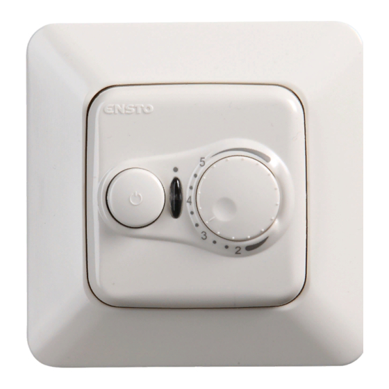
Commissioning and operation, figure 3
5.1. Switch on the heating from the switch A. The signal light B is green when the thermostat is function-
ing and the light turns red when the load is connected.
5.2. Set the desired floor temperature with the adjustment knob C.
5.3. When the thermostat is functioning normally, you can hear a faint click when the load is switched on
and off.
6.
Technical data
Supply voltage
Switch contact
Rated current
Maximum load
Thermostat adjustment range
Operating temperature range
Signal light B
Floor sensor
Floor sensor resistance values
Circuit breaker/fuse
Power in standby
Ingress Protection
Thermostat can control an external relay.
7.
Warranty
The warranty period for Ensto ECO thermostats is 2 years from the date of purchase but no longer than 3
years from the date of manufacture. Warranty conditions, see the product card
8. Disposal
Do not dispose of electrical and electronic devices including their accessories with the household
waste.
•
The product's cardboard packing is suitable for recycling.
•
When a heating system is at the end of the life cycle the cables, conduits and electronic components
must be disposed of properly according to local recycling guidelines.
9.
Figures
1.
Connection diagram
2.
Connection of wires to the thermostat
3.
User interface
4.
Installation and uninstallation
230 V -15%, +10%, 50 Hz
2-pole
10 A
2300 W
10 ... 60 °C
-20 ... +30 °C
green: thermostat on, heating off
red: heating on
NTC, 47 kΩ at 25°C, cable 4 m (extendable to 10 m)
see page 2, table 1 (the sensor is not connected)
max. 16A
< 0,5 W
IP31
RAK40 / 3.5.2021
www.ensto.com.
5 / 12
