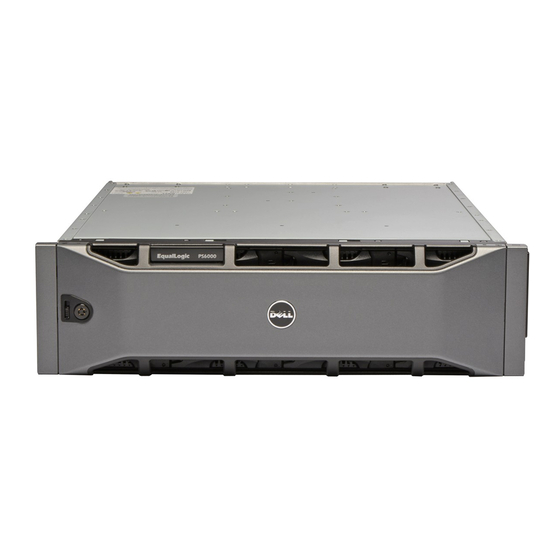
Dell EqualLogic PS6110XS Manuel du matériel - Page 14
Parcourez en ligne ou téléchargez le pdf Manuel du matériel pour {nom_de_la_catégorie} Dell EqualLogic PS6110XS. Dell EqualLogic PS6110XS 50 pages. Equallogic ps series iscsi storage arrays with microsoft windows server failover clusters

Method
Dual-Port Network Adapters Usage
You can configure your cluster to use the public network as a failover for private network communications. If dual-port
network adapters are used, do not use both ports simultaneously to support both the public and private networks.
NIC Teaming
NIC teaming combines two or more NICs to provide load balancing and fault tolerance. Your cluster supports NIC
teaming, but only for the public network; NIC teaming is not supported for the private network or an iSCSI network.
NOTE: Use the same brand of NICs in a team, and do not mix brands of teaming drivers.
Storage Array(s) Cabling Information
This section provides information for connecting your cluster to one or more storage arrays.
Connect the cables between the iSCSI switches and configure the iSCSI switches. For more information see, Network
Configuration Recommendations.
Connect the iSCSI ports from the servers and array(s) to the Gigabit switches, using proper network cables.
For Gigabit iSCSI ports with RJ-45 connectors: use CAT5e or better (CAT6, CAT6a, or CAT7)
For 10 Gigabit iSCSI ports:
•
With RJ-45 connectors: use CAT6 or better (CAT6a or CAT7)
•
With LC connectors: use fiber optic cable acceptable for 10GBASE-SR
•
With SFP+ connectors: use twinax cable
Cabling The Storage For Your iSCSI SAN-Attached Cluster
An iSCSI SAN-attached cluster is a cluster configuration where all cluster nodes are attached to a single storage array
or to multiple storage arrays using redundant iSCSI switches.
The following figures show examples of a two-node iSCSI SAN-attached cluster and a sixteen-node iSCSI SAN-
attached cluster.
Similar cabling concepts can be applied to clusters that contain a different number of nodes.
NOTE: The connections listed in this section are a representative of one proven method of ensuring redundancy in
the connections between the cluster nodes and the storage array(s). Other methods that achieve the same type of
redundant connectivity may be acceptable.
14
Hardware Components
Optical Gigabit or 10 Gigabit Ethernet
network adapters with LC
connectors
Connection
Connect a multi-mode optical cable between the
network adapters in both nodes.
