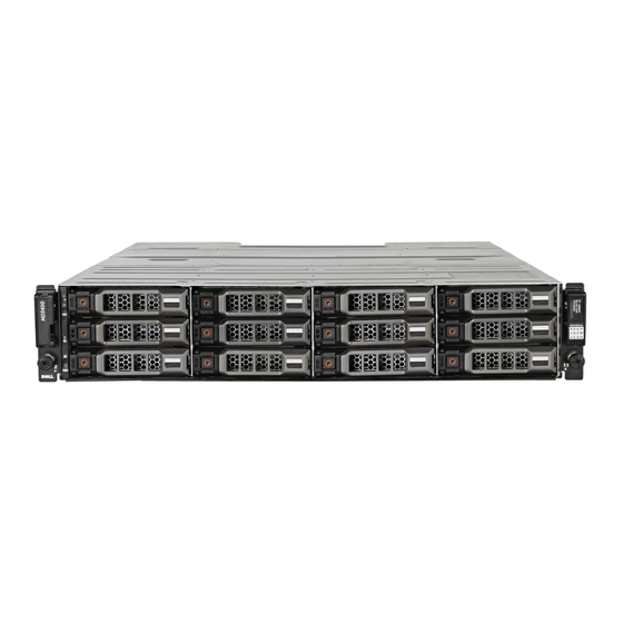
Dell PowerVault MD3420 Manuel du propriétaire - Page 12
Parcourez en ligne ou téléchargez le pdf Manuel du propriétaire pour {nom_de_la_catégorie} Dell PowerVault MD3420. Dell PowerVault MD3420 47 pages. Storage arrays
Également pour Dell PowerVault MD3420 : Manuel de démarrage (8 pages), Manuel de déploiement (27 pages)

Item
LED Type
2
Power supply/
cooling fan fault
3
AC power
4
Power
connector
5
Power switches
(2)
Related Documentation
NOTE: For all PowerVault documentation, go to dell.com/powervaultmanuals.
NOTE: For all Dell OpenManage documents, go to dell.com/openmanagemanuals.
NOTE: For all storage controller documents, go to dell.com/storagecontrollermanuals.
You product documentation includes:
•
Dell PowerVault MD3400/3420/3800i/3820i/3800f/3820f Storage Arrays Getting Started Guide —
Provides an overview of system features, setting up your system, and technical specifications. This
document is shipped with your system.
•
Rack Installation Instructions — Describes how to install your system into a rack. This document is
shipped with your rack solution.
•
Dell PowerVault MD Series Storage Arrays Administrator's Guide — Provides information about
configuring and managing the system using the MDSM GUI.
•
Dell PowerVault Modular Disk Storage Arrays CLI Guide — Provides information about configuring and
managing the system using the MDSM CLI.
•
Dell PowerVault MD3400 and MD3420 Storage Arrays Deployment Guide — Provides information
about deploying the storage system in the SAN architecture.
•
Dell PowerVault MD34xx and 38xx Series Support Matrix — Provides information about the software
and hardware compatibility matrices for the storage array.
12
Icon
Description
If this LED is off, it indicates that the DC output voltage are
not within the limit.
The LED lights amber when the DC output voltage is not
within the limit or a fault with the fan is detected.
If this LED is off, it indicates that no fault condition is
present.
The LED lights green when the AC input voltage is within
the limit.
If this LED is off, it indicates either there is no power or the
AC input voltage is not within the limit.
Connect the external power supply to this connector.
The power switch controls the power supply output to the
enclosure.
