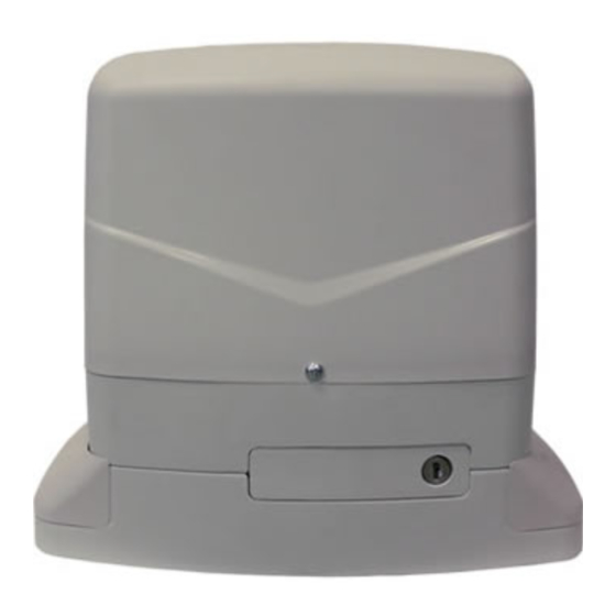
Allmatic KALOS 110 24V Manuel d'instruction - Page 9
Parcourez en ligne ou téléchargez le pdf Manuel d'instruction pour {nom_de_la_catégorie} Allmatic KALOS 110 24V. Allmatic KALOS 110 24V 12 pages.

LIMIT SWITCH FIXING
fig.10
The gate has to be equipped with stop locks at the opening and closing, which prevent the gate derail-
ment.
The stop lock position must assure that the limit switch brackets don't collide with the pinion gear.
Haul the gate manually at the opening leaving, depending on the gate weight, a crack from 30 to 50 mm
between the main gate and mechanical stop.
Fasten the limit switch bracket through the dowels (fig.11) so that the limit switch is pressed (fig.10).
Repeat the operation with the main gate at the closing.
fig.11
19
