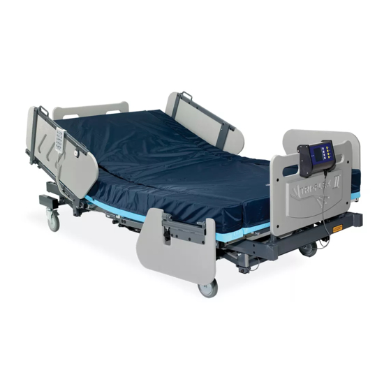
Burke TRI-FLEX II Manuel opérationnel - Page 12
Parcourez en ligne ou téléchargez le pdf Manuel opérationnel pour {nom_de_la_catégorie} Burke TRI-FLEX II. Burke TRI-FLEX II 19 pages. Bed

Operational Instruction
Power and Battery Operation
The electronics system of the Tri-Flex II bed operates
from a low voltage power supply located under the head
of the bed. This control system also includes a battery
back up system to continue operation of the bed in the
event of AC mains failure or during transport. The back
up battery will provide the opportunity for several ad-
justments for patient comfort during power outage or
transport but is not intended for extended use. If the
patient must remain in the bed for an extended power
outage it is recommended that the patient be removed
from the bed.
Trendelenberg Function
To access the Trendelenberg position press and hold
the third Up or Down buttons on the hand pendant to tilt
or reverse the bed as needed.
Bed Elevation (Hi-Lo)
Press and hold the fourth Up or Down buttons on the
hand pendant to raise or lower the bed as desired.
Foot (Up-Down)
Press and hold the second Up or Down buttons on
the hand pendant to raise or lower the foot as de-
sired.
Head Elevation
Press and hold the top Up or Down buttons on the hand pendant to raise or lower the head of the bed as
desired. Maximum head elevation is 60 degrees (see figure 3).
I.V. Poles
If needed, I.V. support poles can be attached to each corner of the bed base frame.
Side Rail Width and Height Adjustments
To attach the side rails to the bed, you must insert the side rail support frame into the horizontal tubes
under the bed. Retract the stop pin by hand until you can pass the frame at least 2" into the bed gatch.
Release the stop pin and continue to insert the support frame to the desired width. To adjust the width,
retract the stop pin and slide the support frame to the in or out position.
To remove the siderail support frame, slowly pull the frame out until it fully engages the stop pin. Manually
retract the stop pin and continue to remove the arm. Normally, the siderail support frame should not be
completely removed for anything other than setup or maintenance.
WARNING: Be sure to fully reengage the stop pin when adjusting the width of the bed. Failure to do
so could result in serious injury and or equipment damage.
WARNING: To maximize the full scope of UL-60601, this bed is intended for patient use in ONLY the
MAXIMUM WIDTH CONFIGURATION. Within the current standard, patient and caregivers are safely
removed from pinch points and moving components which could cause harm. Configurations other
than described reduce the distance to these points which could result in severe personal injury or
equipment damage.
12 TRI-FLEX II BED - OPERATION MANUAL
Figure 2
Figure 3
