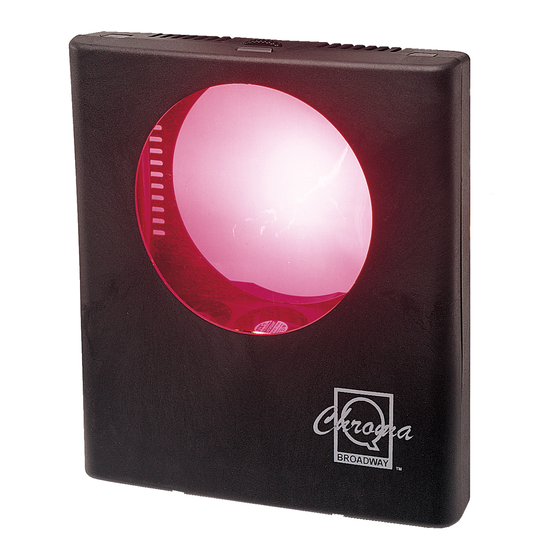
Chroma Broadway Manuel de l'utilisateur - Page 5
Parcourez en ligne ou téléchargez le pdf Manuel de l'utilisateur pour {nom_de_la_catégorie} Chroma Broadway. Chroma Broadway 14 pages.

2.1
Control and power cables
The Chroma-Q utilises an XLR 4-pin cable system. This is used to supply power and data
transfer. Pins 1 and 4 supply 24VDC power; pins 2 and 3 supply ANSI E1.11 USITT DMX 512-A
control protocol with a ground drain wire to the connector shell.
Only genuine Tourflex Datasafe cable is recommended for use with the Chroma-Q colour
changing system (see Product ordering on page 8).
Damage will occur if the power connections short-circuit to the data or ground / shield
connections. When assembling XLR 4-pin cables, heat shrink sleeving should be used on each
individual data pin and the drain wire to prevent short circuits.
Note: It is very important to ensure that the drain wire from the cable shield is connected to
both connector cases.
The cables are wired pin to pin, in the following format:
System Diagram
Each PSU / splitterbox can accommodate two circuits. The total cable length per circuit must
not exceed 60m / 200ft or a Voltage drop will be imposed on the system. The total quantity of
Chroma-Q Broadway units is dependent on the size of the PSU / splitterbox. (See PSU /
splitterbox capacities on page 5 or in the User Manual of each PSU / splitterbox.)
2.2
Setting the DMX address
The DMX address for each unit is set using the 10 way binary switch on the back of the unit
(see page 3). The address switches are pushed up (rotated) to the on setting. Add the address
together to reach the control address required. Example: 1 + 2 = 3, 4 + 64 + 256 = 324.
The Chroma-Q can also be set to a second motor speed. By moving switch 10 on the binary dip
switch to the on (up) position, the inherent speed of the Chroma-Q will decrease by
approximately 50% (ideal for environments that are particularly noise sensitive).
Broadway User Manual
Pin #
1
2
3
4
Chassis
4
Function
0V DC
Control data minus (-)
Control data plus (+)
24V DC (+ve)
Ground bonding
V6.3 December 2006
