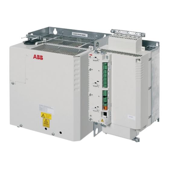
ABB ACSM1-204 Manuel d'installation et de démarrage rapide - Page 6
Parcourez en ligne ou téléchargez le pdf Manuel d'installation et de démarrage rapide pour {nom_de_la_catégorie} ABB ACSM1-204. ABB ACSM1-204 15 pages. Regen supply module
Également pour ABB ACSM1-204 : Manuel (16 pages)

6 Quick installation and start-up guide – ACSM1-204
labeled VARISTOR (1 screw) and FILTER (2 screws) in the regen filter module
(under the cover).
• Fasten the two cable clamp plates included with the regen supply module, one at
the top, one at the bottom. The clamp plates are identical.
Frames A and B:1.5 N·m (13 lbf·in)
Frames C and D: 3 N·m (25 lbf·in)
• Strip the DC cable and resistor cable (if present) so that the cable shields are bare
at the cable clamps. Connect the ends of the cable shields to the ground terminals
using cable lugs. Cover visible bare shield with insulating tape.
• Connect the DC cable and resistor cable to the appropriate terminals.
• Tighten the cable clamps onto the bare cable shields of DC cable and resistor
cable.
• Connect the AC supply conductors and PE conductor to the appropriate
terminals.
• Tighten the cable clamp onto the AC supply conductors and PE conductor, or tie
the conductors to the clamp with a cable tie.
• Frame sizes C and D only: Cut suitable slots on the edges of the connector
covers to accommodate the cables. Refit the covers.
• Connect the filter temperature monitoring cable of the WFU-xx regen filter module
to the thermistor input (X4:8, 9) in the regen supply module.
• Connect the fan control cable of the WFU-xx regen filter module to
DIO1 (X3:14, 15) in the regen supply module.
1.5 N·m (13 lbf·in)
