Miller Coolmate 3.5 Manuel du propriétaire - Page 6
Parcourez en ligne ou téléchargez le pdf Manuel du propriétaire pour {nom_de_la_catégorie} Miller Coolmate 3.5. Miller Coolmate 3.5 13 pages.
9.
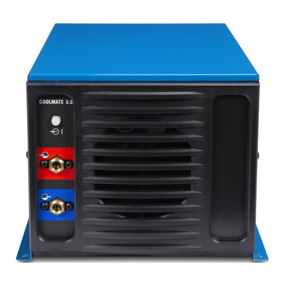
GTAW Connections
1
!
Do not move or operate unit where
it could tip.
To prevent overheating, make sure cooling
unit is positioned so airflow is not restricted.
NOTICE − If welding power source has a
water valve, do not connect hoses to water
valve. Connect hoses as shown.
1
Coolant Out Hose
OM-231 313 Page 4
4
3
2
2
Coolant In Hose
Fittings have 5/8-18 left-hand threads.
Connect hoses with proper fittings as
shown. Some power sources may require
a TIG block.
3
Coolant Tank Cap
4
115 Volt AC Grounded Receptacle
An individual branch circuit capable of car-
rying 15 amperes and protected by fuses
Tools Needed:
5/8 in
or circuit breakers is recommended. Rec-
ommended fuse or circuit breaker size is
15 amperes.
Operation:
Fill tank with proper coolant. Use table in
Section 8 to select proper coolant. Maintain
coolant level at approximately 1 in (25 mm)
below top of filler neck. Connect hoses as
shown. Unit turns on when plugged in.
804 846-A