Miller CST 282 Manuel du propriétaire - Page 17
Parcourez en ligne ou téléchargez le pdf Manuel du propriétaire pour {nom_de_la_catégorie} Miller CST 282. Miller CST 282 42 pages.
4-1.
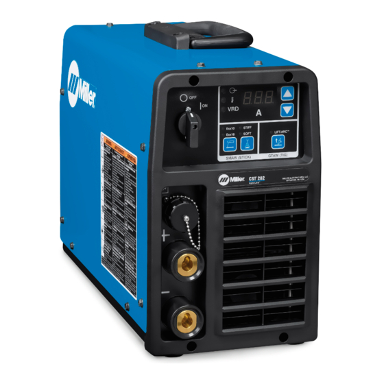
Serial Number And Rating Label Location
The serial number and rating information for this product is located on the back. Use rating label to determine input power requirements and/or
rated output. For future reference, write serial number in space provided on back cover of this manual.
4-2.
Software Licensing Agreement
The End User License Agreement and any third-party notices and terms and conditions pertaining to third-party software can be found at
https://www.millerwelds.com/eula
4-3.
Information About Default Weld Parameters And Settings
NOTICE – Each welding application is unique. Although certain Miller Electric products are designed to determine and default to certain typical
welding parameters and settings based upon specific and relatively limited application variables input by the end user, such default settings are
for reference purposes only; and final weld results can be affected by other variables and application-specific circumstances. The appropriate-
ness of all parameters and settings should be evaluated and modified by the end user as necessary based upon application-specific require-
ments. The end user is solely responsible for selection and coordination of appropriate equipment, adoption or adjustment of default weld
parameters and settings, and ultimate quality and durability of all resultant welds. Miller Electric expressly disclaims any and all implied warran-
ties including any implied warranty of fitness for a particular purpose.
4-4.
Unit Specifications
�
Do not use information in unit specifications table to determine electrical service requirements. See Section 5-7, 5-8, and 5-9 for information
on connecting input power.
�
This equipment will deliver rated output at an ambient air temperature up to 104°F ( 40°C).
A. 208-575 Volts Model
�
The kVA and KW numbers apply at 230 Volts and may be different at other voltages.
Welding
Input
Rated Output
Mode
Power
280A @
31.2 VDC, 35%
Duty Cycle
3
Phase
200A @
28 VDC, 100%
Duty Cycle
STICK
(SMAW)
200A @
28 VDC, 50%
Duty Cycle
1
Phase
150A @
26 VDC, 100%
Duty Cycle
Welding
Input
Rated Output
Mode
Power
280A @
21.2 VDC, 35%
Duty Cycle
3
Phase
200A @
18 VDC, 100%
Duty Cycle
TIG
(GMAW)
200A @
18 VDC, 50%
Duty Cycle
1
Phase
150A @
16 VDC,100%
Duty Cycle
4-5.
Static Characteristics
The static (output) characteristics of the welding power source can be described as drooping during the SMAW and GTAW processes. Static
characteristics are also affected by control settings (including software), electrode, shielding gas, weldment material, and other factors. Contact
the factory for specific information on the static characteristics of the welding power source.
�
Complete Parts List is available at www.MillerWelds.com
SECTION 4 – SPECIFICATIONS
and are incorporated by reference herein.
Max.
Welding
Open-
Amperage
Circuit
Range
Voltage
30-280 A
103
VDC
30-280 A
Max.
Welding
Open-
Amperage
Circuit
Range
Voltage
5-280 A
9.5 VDC
5-280 A
Amperes Input At Rated Load Out-
put, 50/60Hz
208
230
400
460
29.63
26.65
15.71
13.92
18.86
17.09
10.6
9.37
33.7
30.65
17.61
16.18
23.07
20.59
12.97
11.8
Amperes Input At Rated Load Out-
put, 50/60Hz
208
230
400
460
20.77
18.85
11.54
10.22
12.89
11.74
7.42
6.55
22.12
19.71
12.89
11.06
14.84
13.38
8.73
8.63
Dimen-
KVA
KW
sions
575
H:
12.08
10.5
10.1
13.5 in.
(343
mm)
8.02
6.8
6.5
W:
8 in.
(203.2
mm)
14.51
7.0
6.6
D: 18.5
in.
11.15
4.7
4.6
(469.9
mm)
KVA
KW
575
8.95
7.5
7.1
5.49
4.6
4.4
10.61
4.5
4.4
7.72
3.0
2.9
OM-285986 Page 11
Net
Weight
34.6 lb
(15.69
kg)