Burkert 2510 Manuel d'utilisation - Page 9
Parcourez en ligne ou téléchargez le pdf Manuel d'utilisation pour {nom_de_la_catégorie} Burkert 2510. Burkert 2510 13 pages. Device socket
Également pour Burkert 2510 : Mode d'emploi (5 pages), Mode d'emploi (5 pages), Mode d'emploi (5 pages), Manuel d'utilisation (6 pages)
Programming data
I/O configuration
ID code
Default address
Profile
Assignment of the data bits
D3
D2
IN 1
IN 2
2)
2)
2)
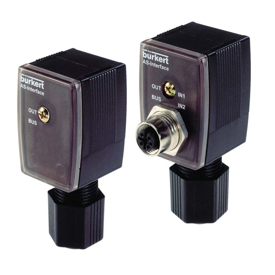
Cable plugs with feedback inputs
B hex (1 output, 2 inputs)
F hex (for assignment see
below)
0
B.F
D1
D0
-
OUT
6.5
LED display for device status
1 2
3 4
Fastening screw
M12 connector, AS-Interface connection
Figure 3: LED display for device status
Item LED
Colour On
1
Input 1
yellow Valve
2
Input 2
3
Status display green
4
BUS
Table 1: Status displays
English
Off
Flashing
Valve not
-
switched
switched
OK
Power OFF Slave address 0
9