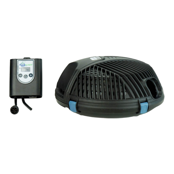
AquaScape 91104 Instruction et entretien - Page 4
Parcourez en ligne ou téléchargez le pdf Instruction et entretien pour {nom_de_la_catégorie} AquaScape 91104. AquaScape 91104 9 pages. Adjustable flow solids-handling pond pump
Également pour AquaScape 91104 : Instructions et entretien (20 pages), Instruction et entretien (16 pages)

sufficient oxygen levels and proper
gas exchange in the pond, helping
to prevent fish loss. For best results
use the AquaForce
®
in combination
with a de-icer. The combination of
the AquaForce
pump and a pond
®
de-icer will further increase the
Pond De-Icer (#39000)
pond's oxygen levels and remove
potentially harmful gases from the water, as well as allow
for a back-up in case one of the devices stops working.
• It is important to not place the AquaForce
on the bottom
®
of the pond during the winter, which may disrupt the
natural thermocline found in the deeper portions of the
pond where the fish overwinter. Instead, place the pump
at least one foot above the
deepest point of the pond. The
rotational ball should be turned
upwards, allowing the water
to bubble at the surface of the
pond. Bricks or stones can be
used, if needed, to raise the
pump to the proper level.
Remote Control and Receiver
Operation
• Receiver Switch – The Receiver includes
a switch that allows the pump to be operated
in the two following modes:
Position 1 - Operated by Remote Control
O
Position 2 - Bypass the Remote and
–
operate at full flow-rate
In the event of a power loss when operating in the Remote
Control setting, the pump will revert to its most recent flow-rate
setting.
• Remote Control – The Remote Control includes the ability
to turn the pump on and off, as well as adjust the flow of
the pump. Make sure the switch on the Receiver is in the
Remote Control setting in order for the Remote to work
properly. The Remote Control has an approximate range of
150 feet. The range of the Remote may be reduced if there
are obstacles between the Remote and Receiver. Use the
included mounting holster provided to provide a location
to store the remote control. It is recommended to mount
the holster in an area that is protected from the outdoor
elements.
☎
6
PLEASE NOTE: The Remote
Control and Receiver are
paired together with their
own unique frequency. For
this reason Remote Control
replacement kits include both
Remote Control and Receiver.
• Battery Installation
1. Remove 4 screws and back cover plate.
2. Place battery into the battery compartment.
Requires 1- 23A 12V battery.
3. Replace back cover and install screws.
2
1
&
3
Pump Operation and Maintenance
• Pump Cage – Do not remove the upper or
lower pump cage while operating the pump.
Failure to operate the pump without the filter
cage or operating the pump with
a broken cage will allow large
debris to enter the pump, causing
TROUBLESHOOTING TIPS
the pump to fail and voiding the
warranty.
• Pump Cage Cleaning –
We recommend inspecting
your pump on a regular basis to
ensure it is functioning properly.
If you notice the flow-rate
diminish, it may be due to the
pump's filter cage becoming
clogged with debris. In many
cases, the pump can simply
be pulled from the pond for
cleaning. Remove any debris
stuck to the pump filter cage
and/or use a garden hose to
spray the cage clean. Always
disconnect the power prior to
performing maintenance on the
pump.
• Remove any debris stuck to the
pump filter cage and/or use a
garden hose to spray the filter
cage clean.
US 1-866-877-6637 |
☎
CAN 1-866-766-3426 | www.aquascapeinc.com
• Internal Pump Cleaning – If you have thoroughly
cleaned the filter cage screens and still have diminished
Decrease
flow rates, then you will need to remove the pump from
Flow
the lower cage and inspect the impeller rotor assembly.
Increase Flow
• Pull the cage release tabs outward to unlock the upper
On/Off
and lower pump cages.
• With the cage tabs released, the upper filter cage can be
lifted to expose the pump.
VIDEO ON AQUAFORCE
PUMP MAINTENANCE &
• Remove the screws
securing the pump
restraining bracket,
allowing the pump to be
lifted from the lower cage.
www.aquascapeinc.com |
• Remove the four screws that hold the water cover
chamber and inspect the impeller rotor assembly.
• If your rotor assembly impeller and internal pump body
have excessive scale build-up, clean with a mild acid,
such as white vinegar or non-abrasive calcium, lime and
rust remover product. A sponge or soft-bristled brush that
won't scratch the stainless steel can be used at this time.
Removing scale build-up will allow your pump to run like
new again.
Replacing the Impeller/Rotor Assembly
When replacing the
AquaForce
®
rotor-impeller
assembly into the pump
chamber, note the proper
orientation. The raised key
on the impeller face plate
should be lined up with the
groove in the pump housing.
PUMP FLANGE PIN
• AquaForce
®
ready for reassembly – The water chamber
cover will only fit back onto the pump with the top of the
tear-drop shapes lining up, along with matching the hole in
the cover with the pin on the face of the pump motor flange.
• For easier pump access,
pull the power cord free
from the strain relief.
PUMP
FLANGE PIN
☎
CAN 1-866-766-3426 |
☎
US 1-866-877-6637
GROOVE
RAISED KEY
PUMP WATER
COVER HOLE
PUMP WATER
COVER HOLE
7
