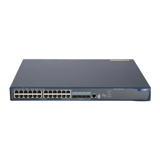
HP 5120-24G-PoE+ EI Manuel de configuration - Page 23
Parcourez en ligne ou téléchargez le pdf Manuel de configuration pour {nom_de_la_catégorie} HP 5120-24G-PoE+ EI. HP 5120-24G-PoE+ EI 39 pages. Hp 5120 ei switch series
Également pour HP 5120-24G-PoE+ EI : Fiche technique (17 pages)

Step
1.
Enter system view.
2.
Configure the description of
a member.
Configuring IRF link load sharing mode
On an IRF port that has multiple links, traffic is balanced across its physical links. You can configure the
IRF port to distribute traffic based on certain criteria, including source IP address, destination IP address,
source MAC address, destination MAC address, or any combination of the criteria. If a criteria
combination is not supported, the system displays an error message.
Configure the IRF link load sharing mode for IRF links in system view or IRF port view.
•
In system view, the configuration is global and takes effect on all IRF ports.
In IRF port view, the configuration is port specific and takes effect only on the specific IRF port.
•
An IRF port preferentially uses the port-specific load sharing mode. If no port-specific load sharing mode
is available, an IRF port uses the global load sharing mode.
Configuring the global load sharing mode
Step
1.
Enter system view.
Configure the global
2.
IRF link load sharing
mode.
Configuring a port-specific load sharing mode
Before you configure a port-specific load sharing mode, make sure you have bound at least two physical
ports to the IRF port.
To configure a port-specific load sharing mode for an IRF port:
Step
1.
Enter system view.
2.
Enter IRF port view.
3.
Configure the
port-specific load
sharing mode.
Command
system-view
irf member member-id description text
Command
system-view
irf-port load-sharing mode { destination-ip
| destination-mac | source-ip |
source-mac } *
Command
system-view
irf-port member-id/port-number
irf-port load-sharing mode { destination-ip
| destination-mac | source-ip |
source-mac } *
19
Remarks
N/A
By default, no member switch
description is configured.
Remarks
N/A
By default, the switch uses source
and destination MAC addresses
for non-IP packets, and uses
source and destination IP
addresses for IP packets.
Remarks
N/A
N/A
By default, the switch uses
source and destination MAC
addresses for non-IP packets,
and uses source and destination
IP addresses for IP packets.
