Dickson Industrial THDx Manuel - Page 3
Parcourez en ligne ou téléchargez le pdf Manuel pour {nom_de_la_catégorie} Dickson Industrial THDx. Dickson Industrial THDx 10 pages. Temperature, humidity & dew point chart recorder

Operating Information
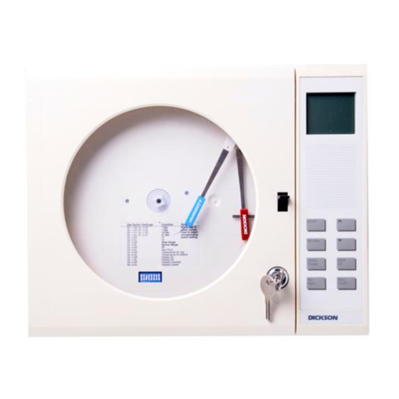
Pens
The blue pen has a longer pen arm and records
humidity or dew point (depending on your dip switch
selection). The red pan has a shorter arm and re-
cords temperature. The pens are offset to allow the
red pen to glide under the blue pen. The blue pen
indicates the correct time and the red pen precedes
it by 3/16 of an inch.
The pens move in increments across the chart
as sensor readings change. The display provides
smoother and faster readings than the pens. At any
given time there may be a slight discrepancy in the
position of the pen and the reading on the display
due to hysteresis.
For visual spot checks the display is more ac-
curate than the pen position but both are within the
stated specifications of the unit.
Pen Adjust
Pen adjustment may be needed if the pens and
display do not match exactly.
1. Make sure the pen lifting bar is lowered and
press the "Pen Home" key.
2. Turn the chart hub clockwise, rotating the chart
3. With a small screwdriver loosen the pen adjust
screw on the pen arms and adjust the pen tips
to the outer most circle on the chart.
4. Retighten the screws. After pressing "Pen
Home" again the pens should now read
correctly with the display.
Probe
The THDx probe sits in the cradle in the back of the
unit. The THDx probe comes with the standard 8"
cord. An extension cord can be ordered to allow for
remote sensing capabilities.
Display Symbols
�������
���
���
E
Alarm is on.
Rev. 06/03
Cord Installation
If you have ordered an extension cord for remote
sensing capabilities follow the instructions for cord
installation listed below.
1. Turn the unit upside down or on its side so that
you can see where the probe connects to the
back of THDx.
2. Twist and pull the black rubber strain relief,
beginning on the back of the recorder body
(see "Instrument Anatomy").
3. Slide the strain relief on the cord
4. Inside you will see a standard connector which
looks like a phone jack. Using a small screw-
driver, press retention tab and the connector
will pop out easily.
5. Remove wand from cradle by sliding upward.
Repeat steps 1 through 3 for the portion of the
cord that connects to the wand.
6. Return the wand to the cradle mounted
position by sliding the wand down into the
cradle until it fits into the grips. The probe can
also be replaced by positioning it in back of the
cradle area pressing it into the cradle until it
snaps in place.
Power Supply
We recommend using AC power with four "D"
batteries installed as a back-up power source. This
ensures that your recording will not be interrupted
when there is a power failure. When the instrument
is using battery power, the unit will update very
slowly to extend battery life. The 120V AC adapter
plugs into the back of the recorder beneath the
probe cradle.
Lo Batt: Low battery indicator
UC: the unit is in "User Calibration" mode. This
is displayed in the upper right hand corner of the
���
display.
Reading Update Indicator: These rectangles will
flash along the bottom of the display as long as the
recorder is taking readings. If you are using batteries
as the power source the update indicator rectangles
will still flash but the rate will be very slow in some
modes and "B" will light on display. The rectangle
furthest to the right is lit continuously when the unit
is using battery power.
MIN: This symbol is displayed when you are setting
a maximum alarm or when you have pressed the
"MIN/MAX" key and the maximum value is being
B
Figure 4
displayed.
MAX: This symbol is displayed when you are setting
a minimum alarm or when you have pressed the
"MIN/MAX" key and the maximum value it being
displayed.
