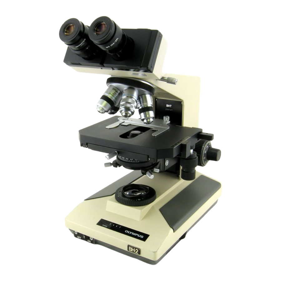
Olympus BH2 Series Démontage, nettoyage et remontage - Page 14
Parcourez en ligne ou téléchargez le pdf Démontage, nettoyage et remontage pour {nom_de_la_catégorie} Olympus BH2 Series. Olympus BH2 Series 45 pages. Phase contrast
Également pour Olympus BH2 Series : Manuel de dépannage et de réglage (46 pages), Démontage, nettoyage et remontage complets (23 pages), Démontage, nettoyage et remontage complets (40 pages), Manuel (6 pages), Manuel d'installation (9 pages)

Once again, place the circular dovetail of the viewing
head mounting disk into the dovetail recess for the
viewing head, using the circular dovetail to depress the
plunger while seating the mounting disk into the recess
(see
Figure
28).
Figure 28 – Place the mounting disk into dovetail recess
Once the mounting disk has been seated into the
dovetail recess, slide the mounting disk towards the
locking thumbscrew so that the plunger shaft protrudes
from the knurled outer barrel of the locking screw (see
Figure
29).
Figure 29 – Slide mounting disk to expose the shaft end
Use a suitable clamp with non-marring jaws to hold the
mounting disk in the slid-over position to keep the end
of the plunger shaft exposed (see
Figure 30 – Clamp mounting disk to keep shaft exposed
Teardown, Cleaning, and Reassembly of the Miscellaneous Parts of the Olympus BH-2 Microscope Frames
Figure
30).
Use needle-nosed pliers to carefully reinstall the e-clip
into the ring groove in the exposed end of the plunger
shaft (see
Figure
31).
Figure 31 – Carefully reinstall e-clip into plunger groove
Loosen the locking thumbscrew and remove the clamp
and mounting disk from the dovetail recess for the
viewing head, to allow the spring-loaded plunger to
fully re-extend into the viewing head recess (see
32).
Figure 32 – Remove mounting disk from dovetail recess
Use a suitable slotted screwdriver to reinstall the
slotted end-screw into the threaded bore of the knurled
outer barrel of the locking screw (see
Figure 33 – Reinstall end-screw into knurled outer barrel
Figure
Figure
33).
Revision 1
Page 14 of 45
