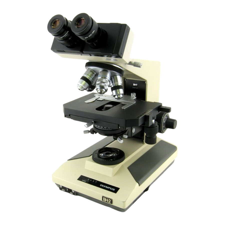
Olympus BH2 Series Démontage, nettoyage et remontage - Page 28
Parcourez en ligne ou téléchargez le pdf Démontage, nettoyage et remontage pour {nom_de_la_catégorie} Olympus BH2 Series. Olympus BH2 Series 45 pages. Phase contrast
Également pour Olympus BH2 Series : Manuel de dépannage et de réglage (46 pages), Démontage, nettoyage et remontage complets (23 pages), Démontage, nettoyage et remontage complets (40 pages), Manuel (6 pages), Manuel d'installation (9 pages)

Figure 106 – Reinstall brass retaining plate onto stator
Using a suitable JIS screwdriver, reinstall the four
m2.6x5 screws to secure the brass retaining plate into
position on the metal diaphragm stator. See
107.
Figure 107 – Reinstall screws to secure the retaining plate
Carefully place the plastic gear collar over the barrel of
the diaphragm rotor, aligning the two holes in the collar
with the two tapped holes in the barrel of the rotor.
See
Figure
108.
Figure 108 – Reinstall plastic gear collar onto the rotor
Teardown, Cleaning, and Reassembly of the Miscellaneous Parts of the Olympus BH-2 Microscope Frames
Using a suitable JIS screwdriver, reinstall the two
m2.6x5 screws to secure the plastic gear collar in place
on the diaphragm rotor. See
Figure 109 – Secure the gear collar with two screws
Using a suitable slotted screwdriver, reinstall the slotted
Figure
stop pin through the hole in the gear collar and into the
field diaphragm rotor. See
Figure 110 – Reinstall the slotted stop pin into the rotor
Test that the field diaphragm opens and closes
smoothly when the gear collar is rotated, and that the
slotted stop pin in the diaphragm rotor hits the upright
slotted stop pin in the brass retaining plate, to prevent
the diaphragm from closing too far.
diaphragm assembly is now ready to be reinstalled into
a microscope and put back into service. See
Figure 111 – Ready to be installed into scope (old style)
Figure
109.
Figure
110.
The field
Figure
Revision 1
Page 28 of 45
111.
