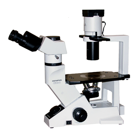
Olympus CKX41 Manuel de réparation - Page 17
Parcourez en ligne ou téléchargez le pdf Manuel de réparation pour {nom_de_la_catégorie} Olympus CKX41. Olympus CKX41 43 pages. Reflected fluorescence system
Également pour Olympus CKX41 : Vue d'ensemble (7 pages), Brochure & Specs (4 pages), Manuel d'instructions (36 pages)

CKX31/CKX41
No.
Parts name
(A)
BINOCULAR TUBE
(B)
COVER
(C)
COVER
(D)
INDICATOR PLATE
(E)
DIOPTER RING
(F)
HELICOID ASS'Y
(G)
SLEEVE ASS'Y
(H)
PRISM ASS'Y
(I)
PRISM ASS'Y
(J)
TORQUE PLATE
(K)
SPRING WASHER
(L)
WASHER
(M)
MOUNT
(N)
RING
(O)
PRISM MOUNT-L
(P)
WASHER
(Q)
PRISM MOUNT-R
(R)
RING
(S)
SHAFT
*Procedure for mounting indicator plate(D):
1) Set the interpupillary distance to the minimum (48mm).
2) Affix the indicator plate(D) such that the indicator plate line may become parallel to the position
indicated by the round convex of helicoid ass'y(F) and the round convex of sleeve ass'y(G).
*Tension adjustment (moving force of interpupillary distance ):
1) Loosen the two scews(*11) that fix the torque plate(J).
2) The tension is increased by turning the torque plate(J) clockwise. It is decreased by turnig
it counterclockwise. ( refer to the figure on the previous page.)
3) Measure the tension using a tension gauge.
Standard: Tension 5 - 15N (OT3223)
* In this manual, left ( right) sleeve indicates the left (right) side with the observed condition.
C. DISASSEMBLY AND ASSEMBLY PROCEDURES
Screw
CUK3X6SA, 4pcs. (*1)
KNW3SA, 4pcs. (*2)
3PUTB2X4SA, 3pcs. (*3)
3PUTB2X4SA, 3pcs. (*4)
ACU3X3SA, 2pc. (*5)
HU3X4SA, 1pc. (*6)
CUK3X6SB, 2pcs. (*7)
CUK3X6SB, 2pcs. (*8)
CUK3X8SA, 2pcs. (*9)
CUK3X8SA, 2pcs. (*10)
AWU3X4SA, 2pcs. (*11)
C-6
Grease Adhesive
Attach it with double coated
adhesive tape.
Refer to D-1.
Revolving axis:
Follow the adjustment procedure
on D-3.
Left/right optical axis:
Follow the adjustment procedure
on D-3.
Push it in the arrow directions
during assembling.
Exit pupil center:
Follow the adjustment procedure
on D-3.
Same as the above
Tension:
standard 5-15N (OT3223)
OT3189
OT3189
OT3189
OT3189
Apply grease to the contacting
surface only.
Absolute optical axis:
Follow the adjustment procedure
on D-3.
Remark
