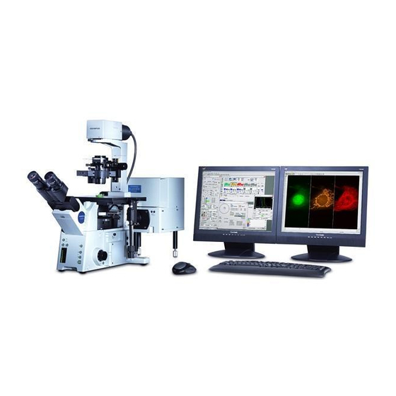
Olympus Fluoview FV1000 Manuel de l'utilisateur - Page 39
Parcourez en ligne ou téléchargez le pdf Manuel de l'utilisateur pour {nom_de_la_catégorie} Olympus Fluoview FV1000. Olympus Fluoview FV1000 42 pages. Confocal microscope
Également pour Olympus Fluoview FV1000 : Vue d'ensemble (28 pages), Instructions abrégées (7 pages), Instructions abrégées (7 pages), Manuel de l'utilisateur (9 pages), Manuallines (3 pages)

Irregularity
Fluorescence image is
dark and noisy.
8. Image is irregularly
blurred or the brightness
is uneven.
9. Observed image is out of
focus.
10. The intensity of part of
the wavelength region of
the spectral
characteristic data of
fluorescence is dropped.
11. Flare is observed.
12. Visual fluorescent light
observation is
impossible.
12. Visual fluorescent light
observation is
impossible.
Cause
The excitation Dichroic Mirror
selection does not match the
observed fluorescence wavelength
and excitation laser wavelength.
The spectral dichroic mirror and
barrier filter selections do not match
the observed fluorescence
wavelength.
The acquisition wavelength region
setting is not suitable for the
observed fluorescence wavelength.
(Spectral detection system only)
The confocal pinhole diameter is too
small.
The scanning rate is too high.
The HV setting is too high.
The width of the acquisition
wavelength region is too small.
Dyeing is too pale.
The specimen or stage is tilted.
The focus is adjusted improperly.
The spectral characteristics of the
fluorescence are affected by those of
the excitation dichroic mirror used in
double excitation.
The glass in use is not fluorescence-
free glass.
The specimen is overstained.
The light path selector in the SU is
not set for the visual observation light
path.
The shutter for the mercury burner is
closed.
The mirror unit incorporating a
dichroic mirror is not present in the
turret of the illuminator.
Troubleshooting Guide
Remedy
Engage a DM optimum for the observed
fluorescence and excitation laser
wavelengths.
Engage a spectral DM and barrier filter
matching the observed fluorescence in
the light path.
Set an acquisition wavelength region
matching the observed fluorescence.
Increase the pinhole diameter.
Decrease the scanning rate.
Decrease the HV and increase the gain.
An alternative remedy is to decrease the
scanning rate and decrease the HV.
Increase the width of the acquisition
wavelength region.
Perform optimum fluorescent dyeing.
Install the specimen and stage properly.
Adjust the focus in visual observation.
Use an excitation DM that does not affect
the spectral characteristic data of
fluorescence.
Use fluorescence-free glass.
Perform optimum dyeing again or
increase the offset value.
Select the visual observation light path.
Open the shutter for the mercury burner.
Engage a mirror unit containing DM in the
light path.
III. TROUBLE Q&A
Page
III. 1 - 3
