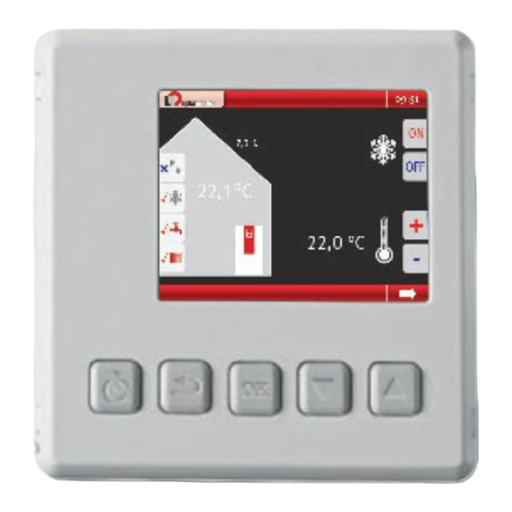
Alpha-InnoTec RBE Manuel d'utilisation - Page 3
Parcourez en ligne ou téléchargez le pdf Manuel d'utilisation pour {nom_de_la_catégorie} Alpha-InnoTec RBE. Alpha-InnoTec RBE 12 pages. Room control unit

Intended use
As a remote control and remote display for certain functions of the heat
pump controller
•
only in conjunction with the heat pump controller
•
for selected products only (for further information, please refer to
the current price list)
Disclaimer
The manufacturer is not liable for any damage or losses resulting from
use of the unit which is not its intended use.
The manufacturer's liability also expires:
•
if work is carried out on the unit and its components contrary to the
instructions in this operating manual.
•
if work is carried out improperly on the unit and its components.
•
if work is carried out on the unit which is not described in this
operating manual, and this work has not been explicitly approved by
the manufacturer in writing.
•
if the unit or components in the unit are changed, modified or
removed without the explicit written consent of the manufacturer.
Customer service
For technical information please contact your local qualified installer or
the manufacturer's local partner.
DE: www.alpha-innotec.de
EU: www.alpha-innotec.eu
Warranty / Guarantee
For warranty and guarantee provisions, please refer to your purchase
documents.
NOTE
Please contact your dealer about all matters concerning warranties and
guarantees.
Deutsch, Installateurhandbuch - RMU 40
Disposal
When withdrawing the old unit from service, comply with the relevant
Allgemeines
local laws, guidelines, directives and standards concerning the recovery,
reuse, recycling and disposal of components.
Mit RMU 40 können Sie Ihre NIBE-Wärmepumpe von ei-
nem Raum im Gebäude aus steuern und überwachen.
Scope of supply
Inhalt
1 RBE
1 RMU 40
mounted frame
made of plastic
Installationsmöglichkeiten
RMU 40 kann auf unterschiedliche Weise installiert wer-
den. Einige Varianten werden im Folgenden aufgeführt.
83032600bUK– Translation into English of the original German operating manual – Subject to technical change without notice.
1 Surface-
2 Screws
1 Abstandsstück
2 Schrauben
aus Kunststoff
2
Deutsch, Install
Allgemeines
General
Mit RMU 40 können Sie Ihre NIBE-Wärm
The RBE can be used to read out, change and optimise the most impor-
nem Raum im Gebäude aus steuern un
tant parameters and operating data conveniently in the home (e.g.
adjustment of the heating temperature or hot water temperature, read-
Inhalt
ing out temperatures).
ENERGY SAVING TIP
€
1 RMU 40
Unnecessarily high flow temperatures in heating or hot water
mode reduce the efficiency of the system, increase stoppage
and pipe losses and therefore increase running costs. With
the room control unit, these temperatures can be set or
optimised to the user's own comfort requirements, easily and
conveniently in the home. To do this, lower the temperatures
Installationsmöglichkeiten
gradually to determine your own personal comfort settings
RMU 40 kann auf unterschiedliche Wei
den. Einige Varianten werden im Folge
The RBE can be used for control with room temperature influence.
The RBE displays the heat pump functions accordingly in the relevant
menu:
•
Heating
•
Hot water
•
Cooling
•
Ventilation
•
Solar thermal energy
•
Swimming pool
•
Photovoltaics
In order to equip the heat pump control with a room control unit, a
control unit with RS485 interface is required:
Raumtemperaturfühler
RMU 40 enthält einen Raumfühler, der dieselbe Funkti-
onsweise wie der Raumfühler im Lieferumfang der Wär-
mepumpe (BT50) aufweist.
So kann gewählt werden, welchen Raumfühler die Wär-
mepumpe zur Anzeige und eventuellen Regelung der
RS485 / LIN-BUS
Raumtemperatur verwenden soll.
Control unit with RS485 and LIN-BUS interface
Der Raumfühler erfüllt bis zu drei Funktionen:
1. Anzeige der aktuellen Raumtemperatur im Wär-
refer to the operating manual of the heat pump controller.
mepumpendisplay.
2. Ermöglicht die Änderung der Raumtemperatur in
°C.
3. Ermöglicht das Aufwerten bzw. Stabilisieren der
Raumtemperatur.
Montieren Sie den Fühler an einem neutralen Ort, an
dem die eingestellte Temperatur gewünscht wird. Als
geeigneter Ort kommt z.B. eine freie Innenwand im
Flur ca. 1,5 m über dem Fußboden in Frage. Der Fühler
darf nicht an der Messung einer korrekten Raumtem-
peratur gehindert werden, z.B. durch die Anbringung
in einer Nische, zwischen Regalen, hinter einer Gardi-
ne, über bzw. in der Nähe einer Wärmequelle, in ei-
nem Luftzugbereich von der Außentür oder in direkter
1 Abstandsstück
aus Kunststoff
1
2
1
2
1
DE
2
1
3
