Axminster Router Elevator Manuel de l'utilisateur - Page 7
Parcourez en ligne ou téléchargez le pdf Manuel de l'utilisateur pour {nom_de_la_catégorie} Axminster Router Elevator. Axminster Router Elevator 16 pages.

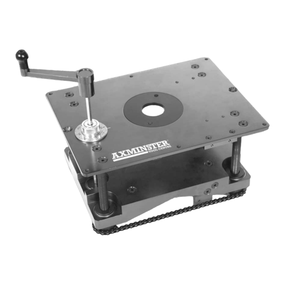
Parts Description of the Router Elevator...
Machine table
This is a 6mm alloy plate 306mm x 229mm, which mounts the threaded
corner pillars and the rotating guide for the winding handle. In each
corner of the plate there is a threaded M6 hole into which the supplied
grub screws can be inserted to enable the table to be levelled (if the
recess is not quite perfect?). There are also 2 x M6 threaded holes for
grub screws midway in the long sides of the table, to support the table
once levelling has been carried out. There are also two countersunk
holes at the extremes of the main axis through which, either screws or
two M6 countersunk bolts (supplied) can be used to fasten the table
down. The hard point for attaching the Digital Readout Scale is
pre-mounted to the table. If the DRO Scale is not to be used; the hard
point can be removed by undoing the 2 securing machine screws. Keep
the parts safely stored in case of a future requirement. If the hard point
is removed, the 'notch' does not need to be cut in the table recess. (As
Fig. A) In the centre of the Table is a 92mm 'clear' diameter hole. A Table
insert reduces the diameter of this hole to 38mm and is held in place by
a 'turn and lock' system, utilising the Nippled 'Y' Spanner. The rotating
guide for the winding handle is located in the lower left quadrant of the
table. Adjacent to the guide is a small line engraved on the face of the
table, this is the reference marker for the floating measurement dial.
Rise and fall
The rise and fall platform has various lands machined in it to mount the
platform
threaded sprocket assemblies (that drive the platform up and down the
corner posts), the drive sprocket assembly that is turned by the winding
handle and an idler sprocket that is used to tension the chain. The chain
is an endless loop that connects all the sprockets. In the centre of the
platform is a 75mm diameter hole. On the underside of the platform is a
circular recess that houses a universal router mounting plate. It is held
in position by four shaped lugs. The lugs are held by a nut and bolt
assembly. On the right side of the platform there is a pre-mounted '
hardpoint' which corresponds to the 'hardpoint' on the table. This is to
enable mounting of the DRO part of the Digital Readout Device. If the
DRO device is not going to be used, the 'hardpoint' can be removed by
undoing the two securing machine screws. Keep the parts stored safely
in case of a future requirement.
Universal router A circular plate approximately 180mm in diameter. It has been pre-drilled
mounting plate
and countersunk with a matrix of all the fixing hole centres for the most
common routers available on the market.
Winding handle
A long hexagonal steel key, with a knobbed handle mounted on the end.
The key is introduced through the guide in the machine table and
introduced into the hexagonal socket in the drive sprocket assembly of
the rise and fall platform. Turning the handle clockwise will raise the
tooling, conversely turning anticlockwise will lower the tooling.
Floating
Termed 'floating' because it is not actually attached to the main
measurement
machine, the Measurement Dial is a shaped 50mm disc that, utilising the
dial
2mm pitch of the rise and fall mechanism has been divided and etched
into 16 equal divisions that correspond to 0.125mm of movement. The
Winding Handle is fed through the Measurement Dial before being
inserted through the table guide and thence into the drive sprocket. The
Measurement dial can be positioned on the Winding Handle key OR the
Winding Handle in the drive sprocket to place the most appropriate
marking against the reference marker on the machine table.
07
