Aybey Elektronik DMP Manuel de programmation et d'installation - Page 2
Parcourez en ligne ou téléchargez le pdf Manuel de programmation et d'installation pour {nom_de_la_catégorie} Aybey Elektronik DMP. Aybey Elektronik DMP 4 pages. Dot matrix display board

GENERAL FEATURES
DMC/DMT/DMP is a dot-matrix vertical display system designed to use for lift cabin and landing
push-buttons. It needs 12-24V DC supply and DMC/DMT board gets all information from controller
system via CANBus and DMP gets from parallel connection (7 Segment, Gray Code, Binary Code,
Counter).DMC is used in fault tolerant CANBus, DMT is used in high speed CANBus.
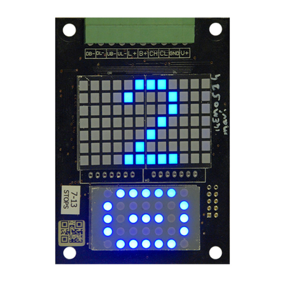
Full character screen is shown below:
After initialization, software version number and ID (in DMC/DMT) is displayed first. Then inputs are
evaluated and related character(s) are displayed according to stored settings. If no input is connected
or all connected inputs are passive then stop 0 character(s) are displayed. (In 7-Segment Mode if no
input is connected or connection is wrong then no character displays; if no communication established
in CANBus mode, then "CE" displays)
PROGRAMMING
On board, there are 3 buttons named as INC (↑), DEC (↓) and ENT. ENT button is used to enter and
exit to/from programming mode, approve and save settings. INC (↑) and DEC (↓) buttons are used to
increase and decrease current value and move up and down in menu.
FLOOR DISPLAY SETTINGS (Only in DMP Board)
IN DMC/DMT board, system gets all floor displays so there is no setting about display (Only in
simulation Mode). On board, user can only set the arrow and Out of Service displays.
In DMP board systems gets information from inputs so user must set floor labels (Not in 7-Segment
Mode). Push and hold ENT button a few second to enter programming mode where arrow icon always
blink. Floor number blinks to set and you can change floor number with INC (↑) and DEC (↓) buttons.
Then with ENT button, right display, left displays and signals icons can be set.
Now display shows upper menu of Floor 0 (bottom floor). To edit Floor 0 display data, push ENT
shortly and enter sub-menu.
Here right char blinks. Now it can be changed by pushing INC (↑) and DEC (↓) buttons. Any number
or letter can be chosen. After selecting right char push ENT shortly and left char starts to blink. By the
same way left char is set. Then set signal icons by pushing ENT.
F/7.5.5.02.89 R:1
DMC/DMT / DMP
2
