FHF Avisa AX04 Manuel - Page 2
Parcourez en ligne ou téléchargez le pdf Manuel pour {nom_de_la_catégorie} FHF Avisa AX04. FHF Avisa AX04 6 pages. Sounder and sounder-strobe-combination
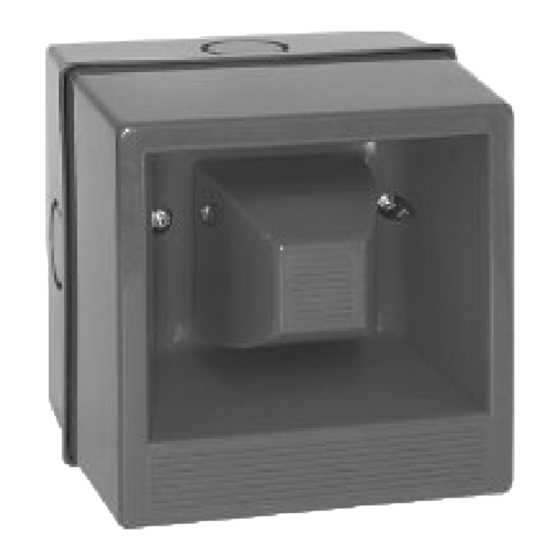
Installation
The sounder or combined sounder strobe units can be
affixed to most surfaces using screws through the holes
of the bottom part.
Supply input
Ensure that the supply is correct for the voltage rating of
the sounder or combined sounder strobe being installed.
Ensure that the supply is OFF before making any con-
nection and wire only in accordance with the terminal
label detail.
Sound selection
Ensure the supply is OFF before proceeding. All dc and
ac units have selectable alarm sounds (see table below
for details) and are selectable by means of the 5 way DIL
switches SW1 for the first stage and SW2 for the second
stage. For dc units the second sound is made available
upon the application of a third wire connected to terminal
TB 1/3 as shown in Fig. 1 while still connected to termi-
nal TB 1/2. Alternatively first and second stage sound
signals can be generated by supply reversal at terminals
TB1/3 and TB1/4 , see Fig. 2. For ac units the second
stage sound is available upon the application of a third
wire L to TB3, see Fig.3.
Mounting
The lower part of housing should be mounted to a suita-
ble surface or to a standard wiring box using any of the
Technical Data AX04
Housing
Colour
Insulation class
Protection degree
Cable gland
Volume
Signals
Temperature range
Operation
Storage
Weight
Operating voltage
Connecting terminals
Technical Data AXL04
Housing
Colour
Insulation class
Protection degree
Cable gland
Volume
Signals
Temperature range
Operation
Storage
Weight
Operating voltage
Connecting terminals
Flash power
Cap colours
2
Polycarbonate
Red, similar to RAL 2002
II
IP 65 acc. to IEC 60529
intended for M20 x 1.5 or Self-sealing grommet
approx. 106 dB(A) (depending on signal tone)
32 different signal tones (see diagrams), 2nd stage can be turned on externally
-25 °C to +55 °C
-40 °C to +70 °C
0.2 kg
24 VDC, 115 VAC, 230 VAC
Clamping capacity 2.5 mm
Polycarbonate
Red, similar to RAL 2002
II
IP 65 acc. to IEC 60529
intended for M20 x 1.5 or Self-sealing grommet
approx. 106 dB(A) (depending on signal tone)
32 different signal tones (see diagrams), 2nd stage can be turned on externally
-25 °C to +55 °C
-40 °C to +70 °C
0.6 kg
24 VDC, 115 VAC, 230 VAC
Clamping capacity 2.5 mm
5 J
red, yellow, green, blue, clear
mounting holes. 20 mm cable entries are provided on all
sides and in the base. To maintain the integrity of the
weather seal, the cable entry must be via a suitable
sealed gland.
Lower part of housing
In order to use the cable entries please remove the
appropriate opening in the lower part of the housing
using a screwdriver. The screwdriver is put into the slot
provided and then given a firm jolt. The pre-punched
plastic plate in the lower part of the housing will then
break off neatly. An appropriate cable entry can then be
mounted or you can guide the cable directly through the
new opening created.
Recycling
The device may be completely recycled as electronic
waste. When the device is disassembled, plastics,
metals and electronics are to be disposed of separately.
EM -Directive
The device complies with the requirements of the
new EMC-directive 2004/108/EC and the low voltage
directive 2006/95/EC.
The conformity with the above directives is confirmed
by the CE sign.
2
solid conductor / 1.5 mm
2
solid conductor / 1.5 mm
2
stranded conductor
2
stranded conductor