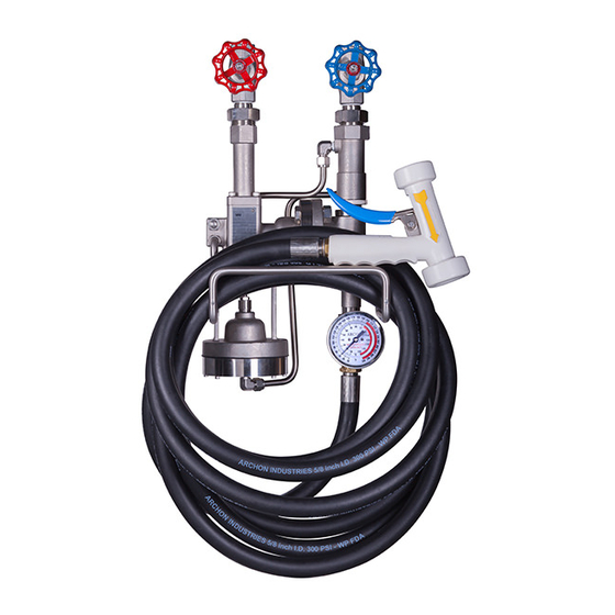
Archon WD2010L Manuel d'installation, d'utilisation et d'entretien - Page 12
Parcourez en ligne ou téléchargez le pdf Manuel d'installation, d'utilisation et d'entretien pour {nom_de_la_catégorie} Archon WD2010L. Archon WD2010L 16 pages. Washdown stations

INSTALLATION/OPERATION/MAINTENANCE INSTRUCTIONS FOR
ARCHON MODELS WD2010L, WD2010, WD2010H WASHDOWN STATIONS
4.2
Steam Section
a.
Holding the steam valve body (11) upside down (note nameplate orientation), insert the threaded end of
the stem assembly (17) into the threaded end of the body until the stem bottoms out on the seat. Assemble
washers (125A) & wavewashers (125) with 2 wavewashers (125) followed by 1 washer (125A) to make a
stack of totally 8 wavewashers and 3 washers. Assemble the stem packing (25), O-ring (39D) and stem
packing gland (19) over the stem. See Figure 4.
Care should be taken when assembling the stem packing over the stem threads so as to not damage the
packing. Turn packing gland (19) clockwise so the underside of the hex contacts the valve body (11)
bonnet.
Note:
Discard and replace any packing that does not freely slide down into the valve packing
chamber. This is caused by flat spots on the outside of the packing.
b.
Assemble nut (4C) onto stem. Thread nut all the way down on the stem.
c.
Assemble O-ring (39E) in groove of connector (103).
d.
Place valve body in a vise with valve seat facing down. Thread connector (103) onto end of stem assembly
(17) by turning in a clockwise direction.
e.
Install upper diaphragm casing (45) over the connector (103) and onto the valve body (11). Secure the
upper diaphragm casing to the valve body using the 2 cap screws (100D).
f.
Assemble the spring (140D), piston (217), diaphragm (182), and retainer (116A) to the bottom end of the
connector using cap screw (100D). Ensure that the piston is installed so that the flared edge of the piston
faces towards the valve stem. Ensure that the piston is secured flush to the connector and that the stem is
fully seated in the body (valve closed).
g.
Thread the assembly of the connector, piston, diaphragm, and retainer on the stem until the flared edge of
the piston bottoms on the inside of the upper diaphragm casing.
h.
With the valve stem fully against the seat, and the piston flared edge bottomed against the inside of the
casing, turn the connector in counter-clockwise direction five-5 complete revolutions. Tighten nut on stem
against the connector to hold in place. (This sets the stroke of the valve from full closed to full open
i.
Align holes in lower diaphragm casing, with holes in diaphragm.
j.
Assemble upper diaphragm casing to the lower diaphragm casing using the eight-8 cap screws (100C). Re-
align upper and lower diaphragm casings at the previously scribed line. Cap screws should be torqued to 3-4
ft-lb.
Figure 4
12
Installation: 1004 Rev 4
Issued: February 7, 2013
