FIAMA SM85.ATEX Manuel d'utilisation et d'entretien - Page 3
Parcourez en ligne ou téléchargez le pdf Manuel d'utilisation et d'entretien pour {nom_de_la_catégorie} FIAMA SM85.ATEX. FIAMA SM85.ATEX 7 pages. Membrane level switch

ATEX level switch
Description
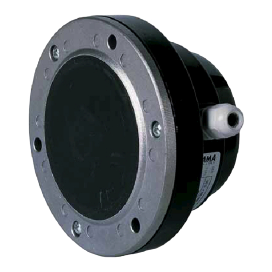
The SM85-ATEX is a simple and economical level switch that
checks the minimum or maximum level in silos and tanks
containing material which is non-sticky in the form of granules or
dust such as rice, cereals, plastic, coffee, sand, cement, etc.
The working principle is simple: the pressure exerted by the
product on the membrane activates the signal micro switch.
Switching sensitivity is adjusted using a screw on the cover.
The unit is installed externally on the wall of the container through
the three holes of the fixing flange. The body of the unit remains
outside of the container, on the side or on the bottom, while the
membrane is in contact with the product.
The product is classified Group II, category 1/2, and installation
zone 20.
The protection mode which is considered is Intrinsic Safety "ia"
which is based on the use of a barrier with intrinsic safety, external
to the unit, which is normally not supplied by FIAMA and is
normally selected and provided by the end user.
The maximum allowed ambient temperature is 80°C.
Installation
The unit can be installed in environments where a potentially explosive
atmosphere, in the form of a cloud of flammable dust, is present
permanently or for long periods within tanks or silos (zone 20).
Installation of the unit must occur in combination with an intrinsic safety
barrier which is able to provide adequate separation between the safe zone and the danger zone.
Analysis of the intrinsic safety risk EN 60079-11
The safety of the unit which is part of this risk analysis is based on the basic principles of the intrinsic safety
protection mode.
This protection consists of a limitation, in the conditions of normal operation or of preventable faults or of rare
faults, the amount of electrical energy of the circuits which are installed in the danger zone and of the connected
instrumentation which is installed in the safe zone so that arcs or sparks or high surface temperatures cannot
ignite the explosive atmosphere.
The unit in the danger zone and the associated electrical plant (intrinsic safety barrier) must be designed to reduce
the open circuit tension (Voc) and the short circuit current (Isc) down to such values which cannot ignite the
explosive atmosphere by opening, short-circuiting, grounding, or heating any part of the circuit.
The implementation of this protection mode is the only accepted method to protect electrical installations which
operate in the danger zones (zone 20).
During implementation of intrinsic safety, it is necessary to consider the following three parts:
•
Unit in the danger zone: membrane sensor with micro switch
•
Safety interface: intrinsic safety barrier
•
Interconnecting cables
An apparatus with switches can be considered a simple apparatus if it does not generate or accumulate more than
1.5V, 100mA, 25mW. Such an apparatus, if powered by a safety interface, which guarantees respect of the
electrical parameters for power supply, is not able to generate sparks that can ignite the gases which have a MIE
value (Minimum Ignition Energy) higher than the energy released during commutation of the contact.
Associated apparatuses
The interfaces between the field and the control room instrumentation are usually called "Barriers"; these protect
the circuits in the danger zone, by limiting the voltage and current, in normal use and fault conditions.
There are two types of intrinsic safety interfaces:
•
Zener barriers
•
Galvanic separation barriers
The fundamental difference is the way that potentially dangerous energy, coming from the control room, is diverted
to prevent entry into the circuits located in the danger zone.
The barriers must by designed and certified according to the requirements of Directive 2014/34/UE and must have
the following marking:
Date: 07/2018
II (1) D [Ex ia]
SM85.ATEX_ing_rev05.doc
SM85.ATEX
ZONA 20
page 3 of 6
