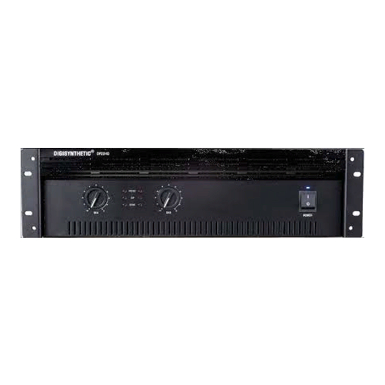
DIGISYNTHETIC DP Series Manuel de l'utilisateur - Page 10
Parcourez en ligne ou téléchargez le pdf Manuel de l'utilisateur pour {nom_de_la_catégorie} DIGISYNTHETIC DP Series. DIGISYNTHETIC DP Series 13 pages. Excellent power amplifier
Également pour DIGISYNTHETIC DP Series : Manuel de l'utilisateur (11 pages)

5.3.3 Signal Limiting Circuit
This internal limiting circuit automatically reduce gain because of a significant deviation
between input and output signal flow, preventing occurrence of gross non-linearity
conditions inside the amplifier caused by overdrive, overload or defect, and keeps the
signal shape unaltered under any conditions. The circuit keep signal flow distortion
under 0.5%, and thus guarantees clean sound and effective speakon protection.
6. Specifications
All amplifier specifications apply to the following settings: Stereo mode with 8-ohm loads
and an input sensitivity of 32dB, unless otherwise specified.
Power Specification
Output Power:
The following specifications are guaranteed minimums for standard 1
kHz power. For more information, see the power matrix in Figures 3.1 through 3.2
(DIGISYNTHETICimum average power @ 0.1% THD +N).
CHANNEL 1
LEVEL CONTROL
LEVEL CONTROL
Fig.2.1 Front Panel Level Control
The following diagram illustrates the actions taken by the Thermal
Management System:
Load Impedance:
8ohms in Bridge-Mono and 4 to 8 ohms in Parallel-Mono mode.
Required AC Mains:
each unit's back panel. All models draw 90 Watts or less at idle.
DP450: (220/50Hz)
Draws up to 10 amps of current.
AC Connector:
An appropriate AC line cord and plug are provided. 110/220 VAC,
50Hz/60Hz units have a standard 3-wire, 15-amp grounded connector (NEMA 5-
15P).
Controls
Power:
A front panel rocker switch is used to turn the amplifier on and off.
Level
: A front panel rotary potentiometer for each channel is used to control the output
level.
CHANNEL 2
Safe with all types of loads. Rated at 4 to 8 ohms in Stereo, 4 to
Current, frequency and voltage requirements are provided on
Heatsink temperature
Temperature Protect Circuit (TPC)
90
c
Automatic
Out put the signal
c
80
°
At 75 C
c
70
60
c
60
DIGISYNTHETIC. fan speed
C
50
c
c
40
c
30
20
c
Min. fan speed,
c
10
TPC normal
c
0
Amplifier: DP Series
Fig.2.2 TPC
90
C
Mute the signal
80 C
TPC Limiter active
Fan speed
Page 9
