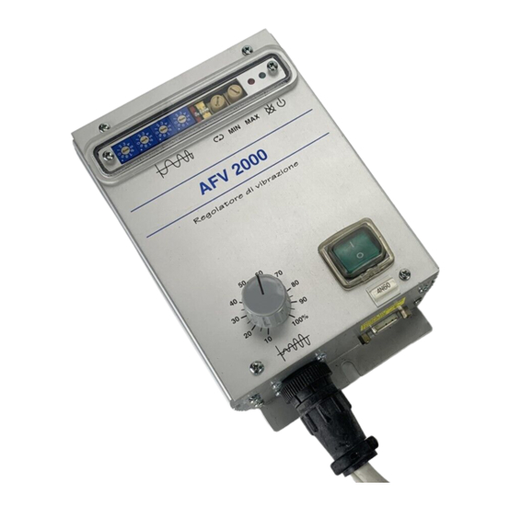
DIGISYSTEM AFV2000 Manuel d'instruction - Page 9
Parcourez en ligne ou téléchargez le pdf Manuel d'instruction pour {nom_de_la_catégorie} DIGISYSTEM AFV2000. DIGISYSTEM AFV2000 9 pages. Variable frequency vibrators power supply
Également pour DIGISYSTEM AFV2000 : Manuel d'instruction (9 pages), Manuel d'instruction (9 pages)

REFERENCE
PIN NUMBER
REF. VOLT.
POT
CCW
CW
0V
RUN
INV. OK
+18V
If voltage reference is coming from external voltage generator, connect 0V at pin 6 and
reference at pin 8.
If voltage reference is coming from external potentiometer 10K, the potentiometer
sliding contact must be connected to pin 7, the CW to pin 5 and the CCW to pin 6.
A switch (SW2 red) on front panel selects automatic or remote start/stop; the switch
ON selects start at power-on, the switch OFF enables start from external command. The
power supply is delivered with this switch ON.
The start-stop control with one external sensor (photocell or other type of sensor) is
available a supply (18 V 50 mA not stabilized).
PNP Sensor: connect supply of sensor between pins 1 (
sensor at pin 3.
NPN Sensor: connect supply of sensor between pins 1 (
sensor at pin 3 and change position of jumper H4 from P to N; H4 is located inside the box,
see opening instructions.
Inverter OK: for remote check of the power supply is available a PNP (18V 20mA) signal
at pin 2; pin 4 is 0V.
OPTIONS WIRING TABLE (M2)
WIRE
SECTION
mmq
8
0,35
7
0,35
6
0,35
5
0,35
4
0,35
3
0,35
2
0,35
1
0,35
SIGNAL DESCRIPTION
Voltage reference (0-5V)
Potentiometer sliding contact (10K)
Potentiometer counterclockwise side (0V insulated)
Potentiometer clockwise side (+5V insulated)
0V insulated for external sensor feeding
Run command from PNP or NPN sensor
Power supply is OK
+18V insulated for external sensor feeding
) and 4 (
+18V
) and 4 (
+18V
9
), connect signal of
0V
), connect signal of
0V
