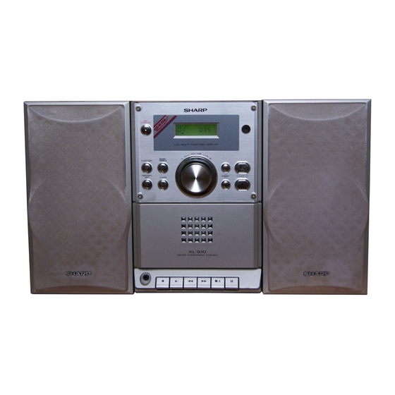
Sharp XL-S10 Manuel d'entretien - Page 4
Parcourez en ligne ou téléchargez le pdf Manuel d'entretien pour {nom_de_la_catégorie} Sharp XL-S10. Sharp XL-S10 44 pages. Sharp deck operation manual xl-s10
Également pour Sharp XL-S10 : Manuel d'utilisation (31 pages)

XL-S10
Audio
CHAPTER 2.
E
Market
XLS10
Service Manual
XL-S10
ADJUSTMENTS
[1] ADJUSTMENT
1. MECHANISM SECTION
• Driving Force Check
Torque Meter
Play: TW-2111
Over 80 g
• Torque Check
Torque Meter
Play: TW-2111
30 to 80 g.cm
Fast forward: TW-2231
70 to 180 g.cm
Rewind: TW-2231
70 to 180 g.cm
• Tape Speed
Test Tape
Adjusting
Specified
Point
MTT-111
Variable
3,000 ± 30 Hz
Resistor in
motor.
TAPE MECHANISM
Figure 1
2. TUNER SECTION
fL: Low-range frequency
fH: High-range frequency
• AM IF/RF
Signal generator: 400 Hz, 30%, AM modulated
Test Stage
Frequency
Frequency
IF
450 kHz
1,602 kHz
AM Band
—
522 kHz
Coverage
AM Tracking
990 kHz
990 kHz
*1. Input: IC301 1Pin
Output: IC301 23Pin
*2. Input: Input is not connected
*3. Input: Antenna
Output:IC301 23Pin
• Check FM VT
Signal generator: 1 kHz, 40 kHz dev., FM modulated
Frequency
Display
87.5 MHz
87.5 MHz
1.5V ± 1.0V
108 MHz
108 MHz
5.0V ± 1.0V
Specified Value
Specified Value
Instrument
Value
Connection
Speaker Ter-
minal (Load
resistance: 6
ohms)
VARIABLE RESISTOR
IN MOTOR
Setting/
Instrument
Display
Adjusting
Connection
Parts
L305
*1
(fL): L306
*2
1.1 ± 0.1 V
L302
*3
Output: TP-VT(IC301 28Pin)
Check
Instrument
Point
Connection
TP-VT
TP-VT
• FM Mute Level
Signal generator: 1 kHz, 40 kHz dev., FM modulated
Frequency
Display
98.00 MHz
98.00 MHz
(30 dBµV)
• FM Detection
Signal generator: 10.7 MHz FM sweep generator
Test
Frequency
Stage
FM IF
10.7 MHz
• FM RF
Signal generator: 1 kHz, 75 kHz dev., FM modulated
Test
Frequency
Stage
FM Band
—
Coverage
FM RF
98.00 MHz
(10 ~ 20dB)
*1. Input: Antenna Output: 23 Pin of IC301
MAIN PWB-A1
L305
AM IF
Figure 2 ADJUSTMENT POINTS
3. CD SECTION
•
Adjustment
Since this CD system incorporates the following automatic adjust-
ment functions, readjustment is not needed when replacing the
pickup. Therefore, different PWBs and pickups can be combined
freely.
Each time a disc is changed, these adjustments are performed
automatically. Therefore, playback of each disc can be performed
under optimum conditions.
2 – 1
Adjusting
Instrument
Parts
Connection
Input: Antenna
Output: Speaker Terminal
Frequency
Setting/
Instrument
Display
Adjusting
Connection
Parts
98.00 MHz
Input: Pin 36 of
IC301
Output: Pin 23
of IC301
Frequency
Setting/
Display
Adjusting
Connection
Parts
87.50 MHz
(fL): L307
*1
1.5 ± 0.1 V
98.00 MHz
L304
*1
FM OSC.
L307
FM BAND
COVERAGE fL
IC301
TP-VT=28Pin
L306
AM BAND
COVERAGE fL
L304
FM RF
CNP301
AM ANT.
L302
AM
Tracking
Instrument
