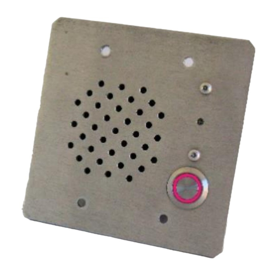
Digital Acoustics INT-IP-2GANG Manuel de démarrage
Parcourez en ligne ou téléchargez le pdf Manuel de démarrage pour {nom_de_la_catégorie} Digital Acoustics INT-IP-2GANG. Digital Acoustics INT-IP-2GANG 3 pages.
Également pour Digital Acoustics INT-IP-2GANG : Manuel de démarrage (4 pages)

Introduction
The INT-IP-2GANG is a PoE powered (802.3af) IP Intercom Call Station that can be configured as a SIP extension
for use with a SIP based phone system. The unit fits in a standard 2-gang electrical box with plaster ring that has a
minimum depth of 2" and is suitable for installation indoors or outdoors in damp locations. It includes:
•
Integrated Microphone - water resistant
•
Integrated Speaker – waterproof cone
•
Security screens protect Microphone and Speaker
•
Integrated vandal resistant Call button with LED
•
Integrated Relay for door/gate activation
•
PoE (802.3af)
•
Includes four stainless steel security screws (T10)
•
User configurable Full or Half duplex operation
•
12 Gauge Stainless Steel Call Station panel
The INT-IP-2GANG is configured using the Digital Acoustics eSIP Configuration utility. This Getting Started Guide
covers basic hardware installation and software configuration of the INT-IP-2GANG.
Installation
The INT-IP-2Gang can be flush mounted into a standard 2-gang electrical box or surface mounted in an optional
surface mount box. For outdoor installations, mount under an eave or use a hooded surface mount box. Please note,
the INT-IP-2Gang can be configured before being installed in the 2-gang box.
•
Connect RJ-45 (B4) to a PoE (802.3af) network
switch or injector. The INT-IP-2GANG will power up
within 5 seconds and request 7.0 watts from the
Power Source Equipment
•
If the relay will be used to activate an electronic door
strike, connect the COM (B2) and either the NO (B1)
or NC (B3) to the door strike
•
The green Link LED (B5) will turn solid. The yellow
Ready LED (B6) and the Call button LED will flash
4x per second
•
Record the ID# from the label on back of the INT-IP-
2GANG for use during software configuration.
•
Optionally, label the panel with one of the extra ID# labels
•
Install the Call Station in the 2-gang electrical box with the call button in the upper left-hand corner so the
RJ-45 connector faces down
•
Fasten using the four security screws (T10)
•
Use a high-quality silicone sealant between the top and sides of the unit and the surface it is mounted to
•
The Call Station LED will continue to flash until configuration is complete
•
Please refer to the INT-IP-2GANG_ReferenceManual available at
https://www.digitalacoustics.com/support/ip7-hardware-talkmaster-software-manuals/ for additional
information on installation
INT-IP-2GANG
SIP Getting Started Guide
Page 1 of 3
