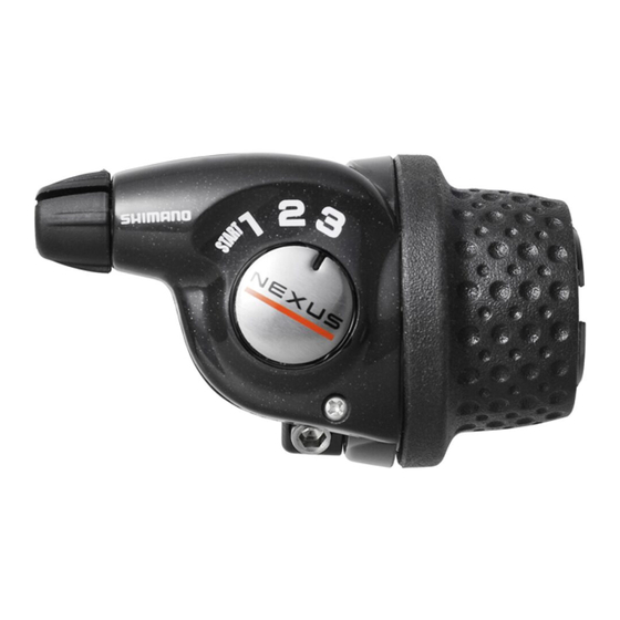
Shimano Bell Crank III Instructions de service
Parcourez en ligne ou téléchargez le pdf Instructions de service pour {nom_de_la_catégorie} Shimano Bell Crank III. Shimano Bell Crank III 4 pages.

WARNING
Obtain, read and carefully service instructions when installing
parts. A loose, worn, or damaged parts may cause injury to the
rider. We strongly recommend that only genuine Shimano
replacement parts be used.
SERVICE INSTRUCTIONS
SL-3S35-
Bell Crank lll
Bell Crank lV
Before use‚ read these instructions carefully‚ and follow them for
correct use.
Be sure to read these service instructions in conjunction
with the service instructions for the Inter-3 hub before
use.
CAUTION
Be sure to shift the lever one gear at a time, and reduce the
force being applied to the pedals during shifting. If you try to
force operation of the shifting lever while the pedals are being
turned strongly, your feet may come off the pedals and the
bicycle may topple over, which could result in serious injury.
Never place your foot on the bell crank. Doing so may cause
problems with gear shifting.
Revo-shift lever operation
Turn the Revo-shift lever to shift to each of the three gears.
Indicator
Pedaling becomes lighter
1
Indicator moves toward
......
1
Starting / Riding on sandy or rough road surfaces/
Riding up slopes / Carrying heavy loads /
Riding into head winds/ When the light is illuminated
......
2
Riding on flat road surfaces
......
3
Riding at high speeds
SI-6E80B
E
Revo-shift Lever
Bell Crank
Pedaling becomes heavier
Indicator moves toward
Revo-shift lever
Installation of the lever
Install the lever as shown in the illustration.
Use a brake lever band with a thickness of
4.3 mm or less so that it does not obstruct
the brake lever and the Revo-shift lever.
1
4 mm Allen key
Tightening torque:
2.5 – 4 Nm {25 – 40 kgfcm}
Installation of the shifting cable
Use a cable with one inner cable drum as the shifting
cable.
3
1.
Set the Revo-shift lever to
Revo-shift lever side
2.
Loosen the cover fixing screw, and then remove the indicator
cover.
The straight section of the
handlebar should be 158 mm
Brake lever
or more in length; attach the
Revo-shift lever to this straight
section.
4
Tighten
Clamp bolt
2
Leave a gap of 0.5 mm
between the Revo-shift
lever and the half grip.
SIS-SP40 (4 mm dia.)
1
.
Set to
1
Cover fixing screw
Indicator cover
Handlebar
22.2 mm
3
Half grip
