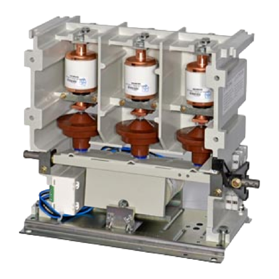
Siemens 3TL81 Manuel d'utilisation - Page 2
Parcourez en ligne ou téléchargez le pdf Manuel d'utilisation pour {nom_de_la_catégorie} Siemens 3TL81. Siemens 3TL81 20 pages. High-voltage vacuum contactors

Inhalt
Beschreibung ..................................................................... 3
Anwendungsbereich ...................................................... 3
Technische Daten .............................................................. 4
Isolationsfestigkeit ............................................................ 6
Maße .................................................................................... 6
Kurzschlußschutz .............................................................. 7
Hochspannungsmotoren .............................................. 7
Komponenten des Motorschutzkreises ........................ 7
Kurzschlußschutz durch Leistungsschalter .................. 9
entsprechend CSA C22.2 .............................................. 9
Lagerung ............................................................................. 9
Montage ............................................................................ 10
Befestigung des Vakuumschützes ............................. 11
Anschließen der Hauptleiter ........................................ 12
Erden des Vakuumschützes ....................................... 12
Anschließen der Klemmenleiste ................................ 13
Anschließen der Hilfsschalter ..................................... 13
Stromlaufpläne ............................................................ 14
Geräteschaltplan .............................................................. 15
Einschaltverklinkung .................................................... 15
Inbetriebnahme ................................................................ 16
Erstes Einschalten ...................................................... 16
Mechanische Einschaltverklinkung ............................. 16
Instandhaltung .................................................................. 17
Wartung ........................................................................ 17
Instandsetzung ............................................................ 17
Reinigung .................................................................... 17
Ersatzteile ......................................................................... 18
Weitere Betriebsanleitungen / Further operating instructions:
Titel
Title
Auswechseln der Schaltröhren
Replacing the interrupters
Auswechseln der elektronischen Sparschaltung
Replacing the electronic economizer
Auswechseln des Hilfsschalterblockes
Replacing the auxiliary switchblock
Mechanische Einschaltverklinkung
Mechanical closing latching
2
Seite
bis Seriennummer 31 670 935
up to serial No. 31670 935
von Seriennummer 31 670 936
from serial No. 31670 936
Contents
Description .......................................................................... 3
Application ..................................................................... 3
Technical data .................................................................... 4
Dielectric strength .............................................................. 6
Dimensions ......................................................................... 6
Short-circuit protection ..................................................... 7
high-voltage motors ....................................................... 7
of the motor circuit ......................................................... 7
Short-circuit protection by circuit-breakers .................... 9
according to CSA C22.2 ................................................ 9
Storage ................................................................................ 9
Installation ........................................................................ 10
Mounting the vacuum contactor ................................... 11
Connecting the main conductors ................................ 12
Earthing the vacuum contactors .................................. 12
Connecting the terminal strip ...................................... 13
Connecting the auxiliary switches ............................... 13
Schematic diagrams ................................................... 14
Internal connection .......................................................... 16
mechanical latching .................................................... 15
Putting into operation ....................................................... 16
First switch-on ............................................................. 16
Mechanical closing latching ........................................ 16
Maintenance ..................................................................... 17
Servicing ...................................................................... 17
Repair work .................................................................. 17
Cleaning ...................................................................... 17
Spare parts ....................................................................... 18
Bestellort / Bestell-Nr.
Place of Order / Order No.
PTD M C P1 Log Berlin
9229 9871 174
9229 9876 174
9229 9873 175
9229 9874 174
9229 9875 174
3ZX1812-TL80-0AN6 / 9229 9870 174 0G
page
2003-03-12
