Bittree 422A32 Manuel de l'utilisateur - Page 8
Parcourez en ligne ou téléchargez le pdf Manuel de l'utilisateur pour {nom_de_la_catégorie} Bittree 422A32. Bittree 422A32 15 pages. Rs-422 64-port active data patchbay

If you would like to daisy-chain devices through the Bittree RS422 Active Data Patchbay, you
may have to use special DE9 cables, with pins 2 and 7 disconnected, to connect the output
remote DE9 ports of the remote devices. This is because certain popular devices, such as the
Sony DVW-M2000 Digital Videocassette Recorder, internally connect drivers at both differential
pairs of pins (pins 3-8 and pins 7-2) of their second, output remote DE9 connector, which is
commonly used to daisy-chain devices in broadcast mode, so that multiple remote devices can be
controlled by a single controller. This practice is in breach of the RS422 protocol, to which the
Bittree patchbay conforms. Therefore, to make the system work correctly, connections between
the second, output remote DE9 connector (labeled REMOTE IN/OUT in the Sony DVW-M2000)
of one of these devices and the patchbay must be accomplished with these special DE9 cables
that do not connect pins 2 and 7 of the end DE9 plugs.
2.2
Front Panel Patchcord Connections
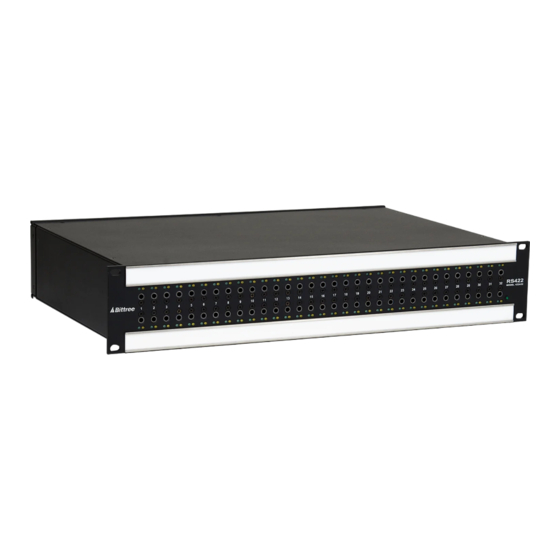
This data patchbay is a "normaling" patchbay. Therefore, devices connected to vertically
aligned DE9 connectors are connected to each other by default, in the absence of a patchcord.
Use standard 3-conductor bantam audio patchcords to connect pairs of jacks on the front panel.
Connecting jacks on the front panel completes data connections between devices connected to
the corresponding DE9 connectors on the rear panel. When a patchcord is inserted into a front
panel jack, the default normaling connection of that jack is broken, and the data is rerouted
through the patchcord.
3.
Verifying and Diagnosing Connectivity
The Bittree RS422 Active Data Patchbay includes circuitry to sense and appropriately auto-
configure its rear panel DE9 ports, according to whether a controller or a remote device is
connected. The auto-configuration process relies on signals that exist at the DE9 connectors of
the connected devices, so these devices must be powered up and configured in the correct remote
mode ("Master" or "Remote"). After the devices connected to the patchbay are correctly
configured, the auto-configuration process is accomplished almost instantaneously, in human
time scale (completed in under one tenth of a second).
3.1
Verifying Connectivity
The Bittree RS422 Active Data Patchbay includes connection-status indicator LEDs designed to
help you verify connectivity or even diagnose connectivity problems, in the unlikely event that
they occur. Two indicator LEDs, one green and one yellow, are mounted above or below each
bantam audio jack on the front panel. A simplified schematic circuit diagram of a vertical slice
of the patchbay (side view), including two front panel jacks and two rear panel DE9 connectors,
is shown in Figure 3.
Page 8 – Bittree RS-422 64-Port Active Data Patchbay User Guide
