Siemens SIMATIC ET 200S Manuel des fonctions - Page 12

Parcourez en ligne ou téléchargez le pdf Manuel des fonctions pour {nom_de_la_catégorie} Siemens SIMATIC ET 200S. Siemens SIMATIC ET 200S 40 pages. Distributed i/o digital electronic module 4do dc24v/2a hf
Également pour Siemens SIMATIC ET 200S : Manuel de l'opérateur (18 pages), Manuel (16 pages), Manuel de l'utilisateur (16 pages), Manuel de l'utilisateur (26 pages), Manuel (37 pages), Manuel (24 pages), Mode d'emploi (4 pages), Mode d'emploi original (19 pages), Mode d'emploi original (20 pages), Manuel (34 pages), Manuel (14 pages), Manuel (24 pages), Mode d'emploi original (17 pages), Mode d'emploi original (19 pages), Manuel (16 pages), Manuel (28 pages), Manuel (12 pages), Manuel (32 pages), Manuel (18 pages), Manuel (12 pages), Manuel (28 pages), Manuel (22 pages), Manuel (22 pages), Manuel (36 pages), Manuel (16 pages)
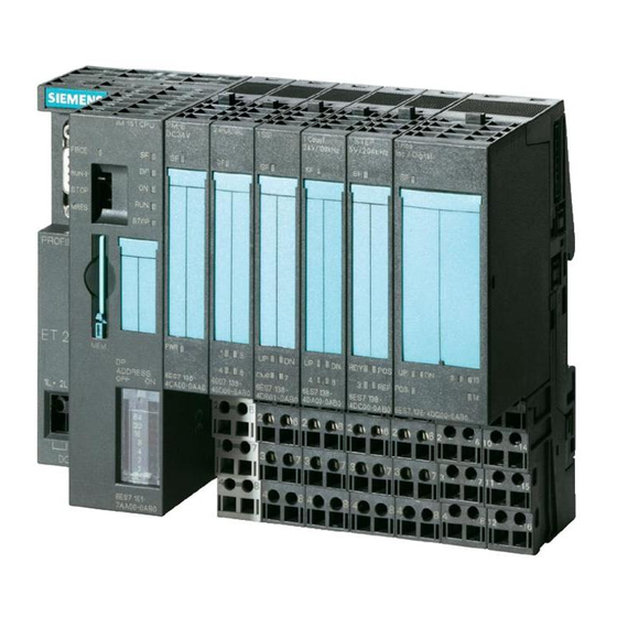
Siemens SIMATIC ET 200S Manuel des fonctions
Description
2.4 Inserting the ET 200S frequency converter into a SIMOTION project
Inserting the frequency converter
1. In SIMOTION SCOUT, open the "User Projects" dialog box with the "Project" > "Open"
menu command. In this dialog box, select your project and confirm with "OK".
2. Open HW Config.
3. In the "HW Config" window, open the hardware catalog with the "View" > "Catalog" menu
command.
4. In the hardware catalog, open the "PROFIBUS DP" folder and the "ET 200S" subfolder and
select, for example, the IM 151-1 Standard interface module (Article No.:
6ES7 151-1AA04-0AB0 or follow-on module).
5. Use a drag-and-drop operation to place the "IM 151-1 Standard" interface module on the
PROFIBUS subnet of your SIMOTION device.
The "Properties - PROFIBUS IM 151-1 Standard Interface" dialog box opens. In this dialog
box, select the address you set on the IM 151-1 (see
Manual) and confirm your selection with "OK".
The selected IM 151-1 Standard I/O device is inserted into the project.
6. The inserted I/O device still has to be equipped with the following modules: PM-D power
module and ET 200S FC frequency converter, consisting of ICU24 closed-loop control
module.
Open the "Motor starter" folder and the "PM" subfolder under "IM 151-1 Standard" in the
hardware catalog. Select the PM-D 24VDC power module.
You insert the frequency converter by selecting in the hardware catalog under
"IM151-1 Standard" (Article No.: 6ES7 151-1AA04-0AB0) in folder "Frequency converters"
the closed-loop control module ICU24 (Article No.: 6SL3244-0SA00-1AA0).
Note
You can disable or enable diagnostic alarms via parameter p8452 in the ET 200S frequency
converter.
7. Save and compile your project.
12
ET 200S Distributed I/O Device
Supplement for the ET 200S frequency converter
Function Manual, 01/2015