Siemens SINAMICS G130 Manuel d'utilisation - Page 11

Parcourez en ligne ou téléchargez le pdf Manuel d'utilisation pour {nom_de_la_catégorie} Siemens SINAMICS G130. Siemens SINAMICS G130 24 pages. Line filter
Également pour Siemens SINAMICS G130 : Manuel d'utilisation (24 pages), Manuel d'utilisation (26 pages), Manuel d'utilisation (46 pages), Manuel d'utilisation (24 pages), Manuel d'utilisation (31 pages), Manuel d'utilisation (30 pages), Manuel d'utilisation (28 pages), Manuel d'utilisation (30 pages), Manuel d'utilisation (22 pages), Manuel d'utilisation (28 pages), Manuel d'utilisation (30 pages), Manuel d'utilisation (34 pages), Manuel d'utilisation (46 pages), Manuel d'utilisation (26 pages), Manuel d'utilisation (26 pages), Manuel d'utilisation (28 pages), Manuel d'utilisation (42 pages), Manuel d'utilisation (46 pages), Manuel d'utilisation (24 pages), Manuel d'utilisation (24 pages), Manuel d'utilisation (30 pages), Manuel d'utilisation (42 pages), Manuel d'utilisation (38 pages), Manuel d'utilisation (46 pages), Manuel d'utilisation (28 pages), Manuel d'utilisation (22 pages)
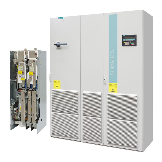
Siemens SINAMICS G130 Manuel d'utilisation

General

The Voltage Sensing Module VSM10 is used to operate a permanent-magnet synchronous
machine without encoder with the requirement for switching to a machine which is already
running (flying restart function).
To commission the function, the permanent-field synchronous machine without encoder
must be input and "Flying restart" activated with p1200.
2.1

Safety information

The 50 mm clearances above and below the components must be observed.
NOTICE
The VSM10 has two terminal blocks to sense the three-phase line supply voltage (X521
and X522). The voltage strength of terminal X521 is a maximum of 100 V (phase-to-phase)
and is used for voltage sensing via a potential transformer. A maximum voltage to be
sensed of up to to 690 V (phase-to-phase) can be directly connected to terminal X522. Only
one of the two terminals X521 and X522 may be used. Nothing may be connected to the
unused terminal.
CAUTION
Connecting cables to temperature sensors must always be installed with shielding. The
cable shield must be connected to the chassis potential at both ends through a large
surface area. Temperature sensor cables that are routed together with the motor cable
must be twisted in pairs and shielded separately.
Voltage Sensing Module 10 (VSM10)
Operating Instructions, 03/2012, A5E02142235A
WARNING
2
9