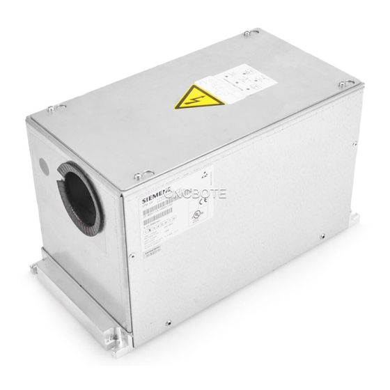
Siemens VPM 120 Manuel d'utilisation - Page 8
Parcourez en ligne ou téléchargez le pdf Manuel d'utilisation pour {nom_de_la_catégorie} Siemens VPM 120. Siemens VPM 120 14 pages. Voltage protection module

Installation:
!
GEFAHR
•
Vor Beginn der Installations- oder Instandhaltungs-
arbeiten ist der Hauptschalter der Anlage auszu-
schalten und gegen Wiedereinschalten zu sichern.
•
In die Anschlussleitungen U, V, W zwischen Um-
richter und VPM dürfen keine Schaltelemente
eingefügt werden.
•
Sind in den Anschlussleitungen U, V, W zwischen
VPM und Motor Schaltelemente erforderlich (z. B.
für Wicklungsumschaltung), darf deren Schaltvor-
gang unter allen Betriebsbedingungen nur strom-
los, bei Motordrehzahl n = 0 und aktiver Impuls-
sperre erfolgen.
Bei Nichtbeachtung kann es zu Lichtbogenbildung
und Brand kommen.
Der Anwender muss eine Risikoanalyse durch-
führen, um die Einhaltung der genannten
Anforderungen nachzuweisen.
•
Vorschaltdrosseln dürfen nur zwischen VPM
und Motor angeschlossen werden.
•
Zum Anschluss des Gerätes ist nur das Öffnen des
Gehäusedeckels gestattet.
Die Installation ist nach Bild 2a / 2b auszuführen.
Die Tabelle „Anschlusstechnik" ist zu beachten.
Unterhalb und oberhalb des Gerätes sind Freiräume von
ca. 200 mm für die Kabeleinführung vorzusehen.
Die Zulufttemperatur, gemessen 10 mm unterhalb des
Gerätes, darf 55° C nicht übersteigen.
Die Einbaulage ist beliebig.
Inbetriebnahme:
Die Inbetriebnahme erfolgt nach den Vorschriften des
Umrichtersystems.
!
GEFAHR
•
Nach Abschaltung aller Spannungen kann noch bis
zu 30 Min. lang gefährliche Spannung anstehen
(Zwischenkreiskondensatoren des Umrichters).
Siemens AG A&D SE WKC
Installation:
!
DANGER
•
Prior to starting any installation or maintenance work,
turn off the main switch of the system and secure it
against being switched back on.
•
Do not add any switching components in the
connection lines U, V, W between inverter
and VPM.
•
If switching components are required in the
connection lines U, V, W between VPM and motor
(e.g. for winding switchover), the switching operation
may be carried out under all operating conditions
only at zero current, at motor speed n = 0 and
pulse disable active.
Otherwise arcing and fire are possible.
The user must carry out a risk analysis to prove
compliance with the mentioned requirements.
•
Series reactors may only be connected between
VPM and motor.
•
When connecting the device, open only the
housing cover.
Install the device as indicated on Fig. 2a / 2b.
Observe the "Wiring Method" table.
Clearances of approx. 200 mm below and above the
device should be provided for cable entry.
Make sure that the supply air temperature, measured
10 mm below the device, does not exceed 55° C.
The mounting position is optional.
Commissioning:
The commissioning is carried out according to the
instructions of the converter system.
!
DANGER
•
When all voltages are switched off,
a hazardous voltage still can be present
for up to 30 min. (DC link capacitors of the
inverter).
A5E00302281B
08 / 2009
Seite 8 von 13
Page 8 of 13
