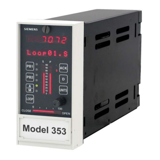
Siemens 353 Manuel de l'utilisateur - Page 20
Parcourez en ligne ou téléchargez le pdf Manuel de l'utilisateur pour {nom_de_la_catégorie} Siemens 353. Siemens 353 20 pages. Multi-purpose training panel
Également pour Siemens 353 : Manuel de l'utilisateur (4 pages)

Operation
3.3 DIGITAL (DISCRETE) INPUTS
Digital inputs for DIN1, DIN2, DIN3, and DIN4 are activated by four single-pole
switches located at the lower right side of the Training Panel and labeled Simulated
Discrete Inputs DIN1 through DIN4. These inputs are powered from the controller's
+26Vdc (Transmitter Power). A logic-1 (ON) state is activated when a switch is ON;
a logic 0 (OFF) state is produced when a switch is OFF.
In Figure 3-2, the DIN switches are identified as SW5, SW6, SW7, and SW8.
3.4 DIGITAL (DISCRETE) OUTPUTS
Two LEDs on the left side of the Training Panel indicate the state of digital outputs #1 and #2
from DIN1 and DIN2. An illuminated LED indicates an active output.
3.5 RELAY OUTPUTS
Two rows of LEDs on the left side of the Training Panel, marked Relay Outputs, indicate the
states of relay outputs ROUT1 and ROUT2. All four LEDs are powered from the controller's
+26Vdc. Each normally open (NO) and normally closed (NC) ROUT contact is connected to
the +26 Vdc through an LED. ROUT1 and ROUT2 common contacts are grounded. A lighted
LED therefore indicates a closed contact.
Both relay outputs use the default selection for relay action. Refer to the Installation section
of UM353-1 for the wiring, noting that the internal +26 Vdc supply is used. An I/O
Expander board must be installed to activate the Relay Outputs (ROUT1 and ROUT2).
3.6 ANALOG INPUT UNIVERSAL
In the middle of the right side of the Training Panel there are two four-screw terminal
strips. These are connected to the AINU1 (top strip) and AINU2 (bottom strip) function
blocks. The user's manual refers to the AINU_ terminals as a, b, c, and d. Looking at the
terminal strips on the training panel, starting with the left connector screw, the
connections are b, a, d, and c as noted on the panel.
The Installation section of UM353-1 describes connection of thermocouple, RTD, Ohms,
and Slidewire devices. An I/O Expander board must be installed in the controller.
3.7 DIGITAL (DISCRETE) INPUT UNIVERSAL
There are two sets of pin jacks on the lower right section of the Training Panel just
under the DIN switches. These jacks are connected to the Digital Input Universal
terminals. Red is positive (+) and black is negative (-).
An I/O Expander board must be installed in the controller to activate these inputs.
Wiring for resistive and inductive loads is shown in UM353-1.
3.8 MODBUS COMMUNICATION
An MMJ-11 connector is provided in the underside of the controller's Display Assembly bezel for Modbus RS232
communication. This connector is active regardless of the controller's installed network communication option
board.
3-4
UM353TP-1
SIMULATED DISCRETE INPUTS
DIN2
DIN3
DIN4
DIN1
ON
OFF
DISCRETE OUTPUTS
DOUT2
DOUT1
RELAY OUTPUTS
NC
NO
ROUT1
NO
ROUT2
NC
UNIVERSAL ANALOG INPUTS
b
a
d
c
AINU1
b
d
AINU2
a
c
UNIVERSAL DISCRETE INPUTS
-
-
+
+
DINU1
DINU2
April 2002
